 01.06.2024, 22:22
 Change Language
 Register
 Login
Login
You are not logged in.
Dear visitor, welcome to Aqua Computer Forum. If this is your first visit here, please read the Help. It explains how this page works. You must be registered before you can use all the page's features. Please use the registration form, to register here or read more information about the registration process. If you are already registered, please login here.

RGBpx cable/pinout identification help (making my own RGBpx to aRGB cables)
Sunday, July 10th 2022, 12:28am
As it looks like its going to take a while for my RGBpx adapter to arrive, I figured I could experiment with my RGBpx extension cable, cut off the end, and splice it into a aRGB cable. Unfortunately I can not find any information showing what wire is ground/power/data. Does anyone have any information on this?
I always seem to have trouble getting an image into a post on this forum. I attached pictures of an RGBpx cable and port pinouts.
RGBPx Pinout.jpg
Farbwerk360 RGBpx Port 2022-0303.jpeg
RGBPx Pinout.jpg
Farbwerk360 RGBpx Port 2022-0303.jpeg

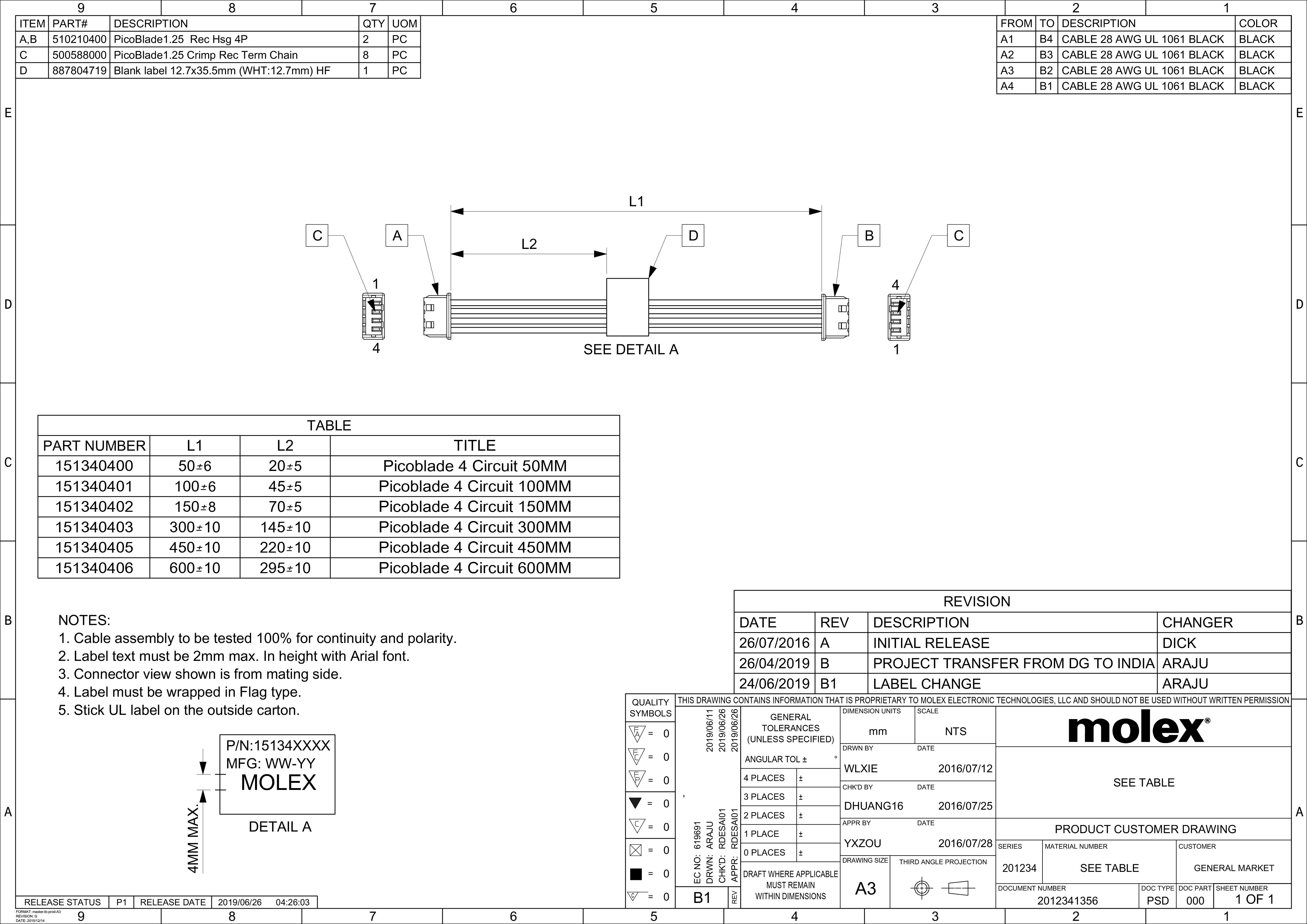
Per Aquacomputer, RGBpx uses Molex PicoBlade 51021-400 plugs. Note that the Aquacomputer pinout is not the same as the pinout of preassembled Molex cables.Is there a generic name for the connector (ie. not RGBpx) that I can search for from electronics suppliers to build my own connectors with? I've seen some references to "picoblade" in random places, but I'm not sure if that's it.
The RGBpx cables are 1:1 cables => pin 1..4 to pin 1..4. PicoBlade pinout is 1 to 4, 2 to 3, 3 to 2, 4 to 1
Hello everyone,
I'll dig out this thread, as I've experienced some problem while moddind 3 pin argb to Quadro RGBpx header.
A little over year ago I've succeed, connected 3x Arctic Cooling fans to D5 Next pump, all still working well.
Recently using same method, identical Molex cable (bought 5 at that point) I've failed miserably - +5V cable literally melted. Prior to installation I've checked everything, there were no shorts, +5 and GND where should be, data was in right place as well. I've connected it to LED strip which was a part of AKWB waterblock to the Quadro controller and seen smoke literally straight away. I can only assume that ledstrip was (probably not anymore) fully functional, as I've bought the block 2nd hand.
Any idea what could go wrong there? As mentioned, tried with multimeter and I'm sure everything was connected properly - GND to single pin in argb strip and +5 to the outer one of the other 2 pins. Mid one was a data.
Is it possible, that Quadro header is faulty somehow? I can try to connect fans to it (from d5) but I will be very unhappy if they will die after that test.
Thanks in advance for any suggestions
D.
That is most unfortunate. As I mentioned in the post above, RGBpx cables are not pinned the same as factory made Molex Pico-Blade cables. If you look at the pin-outs I provided, +5VDC and ground are on the 2 outer pins. If you got this backwards, it would reverse +5VDC and ground, which would probably result in smoke coming out. You may have fried the LED strip and the RGBpx port on the Quadro. If you somehow got +5VDC on the Data pin, that might also fry things. I can't think of any other reason that a cable would melt. Where did the smoke come from? Could you tell? If smoke came from the Quadro, the RGBpx port is probably fried. The PWM fan ports use 12VDC so they are probably OK.Hello everyone,
I'll dig out this thread, as I've experienced some problem while moddind 3 pin argb to Quadro RGBpx header.
A little over year ago I've succeed, connected 3x Arctic Cooling fans to D5 Next pump, all still working well.
Recently using same method, identical Molex cable (bought 5 at that point) I've failed miserably - +5V cable literally melted. Prior to installation I've checked everything, there were no shorts, +5 and GND where should be, data was in right place as well. I've connected it to LED strip which was a part of AKWB waterblock to the Quadro controller and seen smoke literally straight away. I can only assume that ledstrip was (probably not anymore) fully functional, as I've bought the block 2nd hand.
Any idea what could go wrong there? As mentioned, tried with multimeter and I'm sure everything was connected properly - GND to single pin in argb strip and +5 to the outer one of the other 2 pins. Mid one was a data.
Is it possible, that Quadro header is faulty somehow? I can try to connect fans to it (from d5) but I will be very unhappy if they will die after that test.
Thanks in advance for any suggestions
D.
I am not sure what you mean by "connect fans to it (from d5)". You could set the fan port on the Quadro at 100% and put a DC volt meter on it. If you see 12VDC the port is probably OK. If you see nothing, the port is probably blown. I don't think plugging in a PWM fan would fry the fan. At worst, it won't spin.
By connect fans from D5 to Quadro I meant to switch rgbpx plug between them to test if Quadro is working fine.
Fan Speed is controlled by Quadro itself, so fans lighting on D5, fans speed on Quadro - all those are working fine.
Smoke come from the wire, on Pico plug, I guess wire was simply to thin for the current and outer isolation melted.
Header on Quadro is seems to work fine, still +5V as should, no short. No idea how to check Data pin.
As I've wrote before, I'm certain that I done wiring right, no mistakes here. So maybe only problem is that the wire is to thin? But how it could heat up that much to melt outer plastic sleeve?
if your wire has a high enough resistance, it could be "seen" as a load by the quadro, and not create a high enough current to trigger a short circuit protection. But that would be kind of a perfect storm situation where all the stars have aligned to burn your cable.
also you say you plugged and have seen smoke straight away. I hope you do not hot-plug that it would draw current before the plug is fuly inserted = higher resistance.
you'd have to test the waterblock led strip individualy to know if it's okay. no shorts, no exposed traces or solder points that could touch metal etc..
also you say you plugged and have seen smoke straight away. I hope you do not hot-plug that
it would draw current before the plug is fuly inserted = higher resistance.you'd have to test the waterblock led strip individualy to know if it's okay. no shorts, no exposed traces or solder points that could touch metal etc..
I smoked an RGBpx cable once because I used a premade Molex PicoBlade cable.
The premade PicoBlade cables are pinned out 1-4, 2-3, 3-2, 4-1 (see pin-out in schematic below).
The wire guage are 28 AWG UL 1061, if your wire are smaller than 28 AWG, that may be your problem.
Also, double check your pin-out to ensure it is RGBpx compliant, opposite from schematic below.
The premade PicoBlade cables are pinned out 1-4, 2-3, 3-2, 4-1 (see pin-out in schematic below).
The wire guage are 28 AWG UL 1061, if your wire are smaller than 28 AWG, that may be your problem.
Also, double check your pin-out to ensure it is RGBpx compliant, opposite from schematic below.
This post has been edited 3 times, last edit by "InfoSeeker" (Mar 24th 2023, 1:37pm)
According the eBay listing cable is 28awg, but looks very thin.
If you look at picture attached, I've connected +5V to green (that one melted), GND to red and data to black. Yellow was unused. Please let me know if I did it correctly.
IMG-20230324-WA0000.jpg
If you look at picture attached, I've connected +5V to green (that one melted), GND to red and data to black. Yellow was unused. Please let me know if I did it correctly.
IMG-20230324-WA0000.jpg
This post has been edited 2 times, last edit by "darrecky" (Mar 24th 2023, 6:22pm)
I don't see the schematic you referred to.I smoked an RGBpx cable once because I used a premade Molex PicoBlade cable.
The premade PicoBlade cables are pinned out 1-4, 2-3, 3-2, 4-1 (see pin-out in schematic below).
The wire guage are 28 AWG UL 1061, if your wire are smaller than 28 AWG, that may be your problem.
Also, double check your pin-out to ensure it is RGBpx compliant, opposite from schematic below.
According the eBay listing cable is 28awg, but looks very thin.
If you look at picture attached, I've connected +5V to green (that one melted), GND to red and data to black. Yellow was unused. Please let me know if I did it correctly.
Can we see a picture with both connectors, same side up for both?
Pictures of how I've connected it are attached (melted green cable removed, yellow moved into its place for picture purpose). Also there is a pic of melted one as well. I've just push end of the wires of loose cables into an argb extension and secured it with tape for testing only. And that was it due to unexpected outcome of the test itself.
Also if I remember correctly, the smoke did not appear straight away, I guess only after aquasite loaded (or maybe on log in screen) good couple of seconds after power up.
RGBpx to ARGB.jpg
Melted.jpg
Also if I remember correctly, the smoke did not appear straight away, I guess only after aquasite loaded (or maybe on log in screen) good couple of seconds after power up.
RGBpx to ARGB.jpg
Melted.jpg
Silly question but did you ping the ARGB cable to its pins to make sure you attached the right wires together?
the ARGB extension wire did not melt? only the one from the picoblade cable?
if the cable smoked in such spectacular fashion, and the ARGB cable went unscathed, that seems to point at a possible short circuit where you joined them
the ARGB extension wire did not melt? only the one from the picoblade cable?
if the cable smoked in such spectacular fashion, and the ARGB cable went unscathed, that seems to point at a possible short circuit where you joined them
Pictures of how I've connected it are attached (melted green cable removed, yellow moved into its place for picture purpose). Also there is a pic of melted one as well. I've just push end of the wires of loose cables into an argb extension and secured it with tape for testing only. And that was it due to unexpected outcome of the test itself.
Also if I remember correctly, the smoke did not appear straight away, I guess only after aquasite loaded (or maybe on log in screen) good couple of seconds after power up.
[attach]10178[/attach]
[attach]10179[/attach]
It looks like you have the pin numbering on the picoblade connector reversed.
Looking at the connector on the left side of the PICOBLADE SCHEMATIC, you see the side with the two locking bumps up, and the #1 pin to the top.
Your picture shows the opposite side of the connector with label the #1 (yellow), which I believe is actually pin #4
This post has been edited 1 times, last edit by "InfoSeeker" (Mar 24th 2023, 7:35pm)
I believe I did it properly. Bumps as per 1st attachment are underneath, not on top. So it is slide to the socket as on 2nd attachment.
Bumps.jpg
Fit.jpg
I can only see 3 options here:
1. due to poor connection (bare wires slided into argb plug) there was connection issue - as Remayz suggested in earlier post "if your wire has a high enough resistance, it could be "seen" as a load by the quadro, and not create a high enough current to trigger a short circuit protection"
2. led strip was faulty from the beginning
3. RGBpx connector (or logic/controller) in Quadro was faulty - bought it 2nd hand, so maybe someone experimented on it.
Quote Remayz the ARGB extension wire did not melt? only the one from the picoblade cable?
No, all other cables / plugs seems looks completely fine, no sign of any overheating
If everything was connected as should I can try again, all properly soldered this time, but simply I'm a bit scared that I will fry something expensive here.
Sorry, but haven't figured out how to quote someone :/
This post has been edited 1 times, last edit by "darrecky" (Mar 24th 2023, 8:57pm)
I find myself getting confused trying to figure out if you somehow reversed +5VDC and ground from the various pictures. Also, you are using Red for Ground and Yellow for +5VDC which is kind of confusing. It seems like you know what you are doing, and have successfully done this before, but this is very easy to screw up. Now it is difficult to test because you don't know if the Quadro RGBpx port and/or the LED strip is fried.I believe I did it properly. Bumps as per 1st attachment are underneath, not on top. So it is slide to the socket as on 2nd attachment.
[attach]10181[/attach]
[attach]10182[/attach]
I can only see 3 options here:
1. due to poor connection (bare wires slided into argb plug) there was connection issue - as Remayz suggested in earlier post "if your wire has a high enough resistance, it could be "seen" as a load by the quadro, and not create a high enough current to trigger a short circuit protection"
2. led strip was faulty from the beginning
3. RGBpx connector (or logic/controller) in Quadro was faulty - bought it 2nd hand, so maybe someone experimented on it.
Quote Remayz the ARGB extension wire did not melt? only the one from the picoblade cable?
No, all other cables / plugs seems looks completely fine, no sign of any overheating
If everything was connected as should I can try again, all properly soldered this time, but simply I'm a bit scared that I will fry something expensive here.
Sorry, but haven't figured out how to quote someone :/
If you are positive that there are no shorts, you could (carefully) put a DC volt meter on the +5VDC and Ground pins of the Quadro and see if you get +5VDC on pin 4 relative to pin 1. The RGBpx port on the Quadro is rotated compared to a Farbwerk360. As you look at the Quadro, pin 1 (Ground) is the top pin (the pin closest to the aquabus connector). Pin 4 (+5VDC) is the bottom pin (closest to the bottom of the Quadro). If you get +5VDC on pin 4 relative to pin 1, then remove power, plug in your cable, and (assuming nothing starts to melt). put the meter on the ARGB connector on the other end. On that connector, the +5VDC contact is the one under the arrow. In your ARGB to RGBpx photo, the +5VDC pin has a yellow wire coming out of it. In your Bumps photo, the Red wire would go to ground and the Yellow wire would go to +5VDC. It looks like you wired it correctly to me, which I realize is not very helpful.
Quadro.jpg
RGBpx to ARGB-1.jpg
Bumps-1.jpg
To quote a post, click on the Quote button on the right side (next to Report) then select "Quote Post". You can start typing your response right after the /quote in square brackets at the very end of the quoted text. Quoting parts of a post or posts that have quotes in them can get tricky. This forum is kind of old school so you have to be careful if you want to delete parts of the post you are quotting.
This post has been edited 1 times, last edit by "Speedy-VI" (Mar 25th 2023, 12:38am)
Similar threads
-
 English forum »
-
 ARGB is a mess...
(Jun 24th 2022, 5:35pm)
ARGB is a mess...
(Jun 24th 2022, 5:35pm)
-
- English forum »
-
What do I need to control this many fans?
(Jul 26th 2021, 5:06pm)
-
- English forum »
-
Making Custom ARGB to RGBpx Cable
(May 25th 2021, 4:34am)
-
- English forum »
-
Octo / Farbwerk connectivity
(May 8th 2021, 1:57am)
-