 27.04.2024, 01:04
 Sprache ändern
 Registrieren
 Anmelden
Sie sind nicht angemeldet.
Lieber Besucher, herzlich willkommen bei: Aqua Computer Forum. Falls dies Ihr erster Besuch auf dieser Seite ist, lesen Sie sich bitte die Hilfe durch. Dort wird Ihnen die Bedienung dieser Seite näher erläutert. Darüber hinaus sollten Sie sich registrieren, um alle Funktionen dieser Seite nutzen zu können. Benutzen Sie das Registrierungsformular, um sich zu registrieren oder informieren Sie sich ausführlich über den Registrierungsvorgang. Falls Sie sich bereits zu einem früheren Zeitpunkt registriert haben, können Sie sich hier anmelden.

LCD Modification
Around a year and a half ago I built an external LCD system monitor, unfortunately because I used standard paint on aluminum the paint really didn’t hold that well and started to look a bit shabby so I took it apart and the LCD lived in my bits box for about a year. So what with the new project I decided to take it out and dust it off. I originally wanted to put it on top of the case like the pump controller but unfortunatly I completly ran out of room.
Although saying that I'm tempted to remove the pump controller and move it to the bay drive where the LCD is and switching the LCD to where the pump monitor is..... but thats for another day as it will require me to strip the system down completely.......Anyway!

Now this LCD is excellent and the software and controller I was using for it was very good as well and I would recommend anyone who is using an LCD to use it Click Me! as it’s a great utility and since I last used it the amount of things you can now do are amazing!
Now I wasn’t too happy about the brass pins holding the front together and the face plate was too busy as well so I decided to go to work on this like I had the optical drives and the bezel plates of the case and again the objective was to get a nice clean finish as I didn’t was to detract from the clean finish I had achieved with the optical drives. Again I used exactly the same process I used to fabricate all the other face plates although this time I had to cut larger holes for the power button and light switch.
The Optical drive isn't screwed in

Now the most amazing thing about this LCD is the controller and software, I have looked for everywhere and this is the best out there in my opinion, It’s easy to use, works with most applications and software most of us are using and it also allows you to customize and tweak the settings and displays as you want them. Including graphics!
Now the first thing I did was draw my graphics, the kind people over at V.L Systems have already added some of the more popular designs for you, Intel, AMD, ATI, NVIDIA and others and they are easily changed or modified to suit your needs.

As you can see I have add the appropriate text to the image.
So this is a system mod right? So I didn’t want to have the stock images on my system so I went about changing them for my needs. The first thing I did was go about designing the opening screen using the same wave style that will be used in the window etching. This is harder than what it seems as you have to tell the system where to pull the image from for each line so it’s a little tricky getting the image to line up. But once you get the hang of it you can do some crazy things!

How it looks on the LCD

Around a year and a half ago I built an external LCD system monitor, unfortunately because I used standard paint on aluminum the paint really didn’t hold that well and started to look a bit shabby so I took it apart and the LCD lived in my bits box for about a year. So what with the new project I decided to take it out and dust it off. I originally wanted to put it on top of the case like the pump controller but unfortunatly I completly ran out of room.
Although saying that I'm tempted to remove the pump controller and move it to the bay drive where the LCD is and switching the LCD to where the pump monitor is..... but thats for another day as it will require me to strip the system down completely.......Anyway!
Now this LCD is excellent and the software and controller I was using for it was very good as well and I would recommend anyone who is using an LCD to use it Click Me! as it’s a great utility and since I last used it the amount of things you can now do are amazing!
Now I wasn’t too happy about the brass pins holding the front together and the face plate was too busy as well so I decided to go to work on this like I had the optical drives and the bezel plates of the case and again the objective was to get a nice clean finish as I didn’t was to detract from the clean finish I had achieved with the optical drives. Again I used exactly the same process I used to fabricate all the other face plates although this time I had to cut larger holes for the power button and light switch.
The Optical drive isn't screwed in
Now the most amazing thing about this LCD is the controller and software, I have looked for everywhere and this is the best out there in my opinion, It’s easy to use, works with most applications and software most of us are using and it also allows you to customize and tweak the settings and displays as you want them. Including graphics!
Now the first thing I did was draw my graphics, the kind people over at V.L Systems have already added some of the more popular designs for you, Intel, AMD, ATI, NVIDIA and others and they are easily changed or modified to suit your needs.
As you can see I have add the appropriate text to the image.
So this is a system mod right? So I didn’t want to have the stock images on my system so I went about changing them for my needs. The first thing I did was go about designing the opening screen using the same wave style that will be used in the window etching. This is harder than what it seems as you have to tell the system where to pull the image from for each line so it’s a little tricky getting the image to line up. But once you get the hang of it you can do some crazy things!
How it looks on the LCD
Now this controller has a wide variety of functions, The people over at VL Sys have put it together so that it can interact with Win Amp, WMP, MBM5 and your e-mail service provider! As well as all the usual functions like; Time, Real Time CPU clock, CPU-RAM usage and other system reporting tools and these can be either scrolled through manually using the system tray Icon or as a user specified cycle going through everything you selected.
As I said the amount of things it can do are vast so I will only show you a few that that are standard or modified that us O/C’ers and Moders would use!
CPU Reporting
These are the CPU reporting images and screens the 1st one is modified for my CPU.

Graphics Card
Again these are modified for my Card using the ATI template.

System Reporting
Loads of options and extras this is just a sample there is probably over 100 options a screens to choose from!

WMP & Win Amp
Now this is a really nice option especially if you use you system as a stereo or home entertainment system which I often do.

Again I'm really tempted to take everything apart and reinstall this at the top of the case..... .but I think for now I have to much to do on the rest of the project!
As I said the amount of things it can do are vast so I will only show you a few that that are standard or modified that us O/C’ers and Moders would use!
CPU Reporting
These are the CPU reporting images and screens the 1st one is modified for my CPU.
Graphics Card
Again these are modified for my Card using the ATI template.
System Reporting
Loads of options and extras this is just a sample there is probably over 100 options a screens to choose from!
WMP & Win Amp
Now this is a really nice option especially if you use you system as a stereo or home entertainment system which I often do.
Again I'm really tempted to take everything apart and reinstall this at the top of the case..... .but I think for now I have to much to do on the rest of the project!
[Size=3]Video Card Ram Sink Mod[/size]
Well I had a busy day yesterday over in Akihabara looking for bits for the case,
I didn’t buy anything major which the wife was shocked at but I did pick up some great lights for the case and also 2 heat sinks for the following mod!
Now I have noticed the serious lack of dedicated GPU memory heat sinks out there, and I was particularly after a certain style….. Much to my annoyance they aren’t made. So I decided to make my own.
Now Alpha make some great CPU heat sinks and so I decided to see what they had on offer for passive Northbridge cooling and this is what I found:

Now I love the long fins on this heat sink as I wanted to reduce the noise in the case I had to go without the hurricane inducing fan array most of us have
Now the next step was to get them to fit on the GPU memory and to do this I used the Black and Decker again now although the bottom of these heat sinks don’t have a mirror finish I didn’t want to slip and put a gouge in them so I went slowly and surely until I had my eight heat sinks.

Next step was to clean up the edged using a file and then 800 to 1000 grit sand paper to restore the finish to the edges.
After I had done that I lapped the bottom of each heat sink starting at 800 then working up to 2000 grit paper and then finished off using the Holts cream.
The final step was to attach the heat sinks to the actual card now as I’m not sure what the future cooling method of this card would be I decided not to attach them using 100% A/S adhesive but to only use it on the corners while the rest of the area would be covered in standard A/S 3.

Not sure if this is the good memory or not but it was actually one of the 1st 9800 Pro’s on the market here in Japan. So if you know if this memory is any good please tell me!
Once that was done it was time to grab some lunch and wait for it to cure.

After a couple of hours in the sun I flipped it over and attached the other side using the same method of putting the adhesive in the corners only so that I might be able to remove the heat sinks at a later date.

The width of the card has been extended but that’s not really a problem as there is nothing in the case near it to conflict with the heat sinks.
Once I have it is all cured I’m going to see how much of an overclock I can get on it!
Well I had a busy day yesterday over in Akihabara looking for bits for the case,
I didn’t buy anything major which the wife was shocked at but I did pick up some great lights for the case and also 2 heat sinks for the following mod!
Now I have noticed the serious lack of dedicated GPU memory heat sinks out there, and I was particularly after a certain style….. Much to my annoyance they aren’t made. So I decided to make my own.
Now Alpha make some great CPU heat sinks and so I decided to see what they had on offer for passive Northbridge cooling and this is what I found:
Now I love the long fins on this heat sink as I wanted to reduce the noise in the case I had to go without the hurricane inducing fan array most of us have
Now the next step was to get them to fit on the GPU memory and to do this I used the Black and Decker again now although the bottom of these heat sinks don’t have a mirror finish I didn’t want to slip and put a gouge in them so I went slowly and surely until I had my eight heat sinks.
Next step was to clean up the edged using a file and then 800 to 1000 grit sand paper to restore the finish to the edges.
After I had done that I lapped the bottom of each heat sink starting at 800 then working up to 2000 grit paper and then finished off using the Holts cream.
The final step was to attach the heat sinks to the actual card now as I’m not sure what the future cooling method of this card would be I decided not to attach them using 100% A/S adhesive but to only use it on the corners while the rest of the area would be covered in standard A/S 3.
Not sure if this is the good memory or not but it was actually one of the 1st 9800 Pro’s on the market here in Japan. So if you know if this memory is any good please tell me!
Once that was done it was time to grab some lunch and wait for it to cure.
After a couple of hours in the sun I flipped it over and attached the other side using the same method of putting the adhesive in the corners only so that I might be able to remove the heat sinks at a later date.
The width of the card has been extended but that’s not really a problem as there is nothing in the case near it to conflict with the heat sinks.
Once I have it is all cured I’m going to see how much of an overclock I can get on it!
Well I'm waiting on everything and nothing!
Spoke to the guys at Lunagenlabs.com and they have confimred shipment so I'm hoping they arrive before Golden Week (A weeks worth of National Holidays where the entire population *or close to it* go on holiday) other wise I'm in for a long wait!
I got an e-mail from FrozenCPU.com telling the person that was dealing with my window etching o longer works for them so i have had to start that process all over again! So i have no idea when that will be finished and shipped.:mad:
Any way back to case mods, As this is a complete system mod I decided to make a new case badge in the theme already laid out.
Basically this one was easy as you can buy premade Kamon in most stationary shops so I wipped out the sand paper and removed the offending "Cooler Master" case badge.

I then applied the decal, now these are great as they are made by 3M so the bonding on the back is extremely strong so after about 10 minutes it's set and will be dificult to remove.

Pretty easy 30 seconds to do and the results are great!

Now where the hell are those fan grills!
Spoke to the guys at Lunagenlabs.com and they have confimred shipment so I'm hoping they arrive before Golden Week (A weeks worth of National Holidays where the entire population *or close to it* go on holiday) other wise I'm in for a long wait!
I got an e-mail from FrozenCPU.com telling the person that was dealing with my window etching o longer works for them so i have had to start that process all over again! So i have no idea when that will be finished and shipped.:mad:
Any way back to case mods, As this is a complete system mod I decided to make a new case badge in the theme already laid out.
Basically this one was easy as you can buy premade Kamon in most stationary shops so I wipped out the sand paper and removed the offending "Cooler Master" case badge.
I then applied the decal, now these are great as they are made by 3M so the bonding on the back is extremely strong so after about 10 minutes it's set and will be dificult to remove.
Pretty easy 30 seconds to do and the results are great!
Now where the hell are those fan grills!
Update on the overclocking of the Graphics Card
Card ATI Radeon 9800 Pro 128MB
Core Clock: 450 MHz
Memory Clock: 760 MHz
3DMark Score: 6332
These are the first oc's I have done so I might be able to go higher...... I will keep you all posted.But I'm glad I put those heat sinks on the memory as they are warm which means they are working! Also I'm sure I can score higher If I do some system tweaking so any Benchmark pro's out there let me know all the window and bios setting tweaks I need to know!
I'm going to have to Mod one of the heat sinks though as It conflicted with outflow of the GPU water block so it's currently minus one heat sink! as you can see!

The water block doesn't interfere with the Heatsink just the tubing so I'm currently moding the heatsink for a work around this problem
Well that as you can see proves that even with the most well thought out plans something gets missed!
Card ATI Radeon 9800 Pro 128MB
Core Clock: 450 MHz
Memory Clock: 760 MHz
3DMark Score: 6332
These are the first oc's I have done so I might be able to go higher...... I will keep you all posted.But I'm glad I put those heat sinks on the memory as they are warm which means they are working! Also I'm sure I can score higher If I do some system tweaking so any Benchmark pro's out there let me know all the window and bios setting tweaks I need to know!
I'm going to have to Mod one of the heat sinks though as It conflicted with outflow of the GPU water block so it's currently minus one heat sink! as you can see!
The water block doesn't interfere with the Heatsink just the tubing so I'm currently moding the heatsink for a work around this problem
Well that as you can see proves that even with the most well thought out plans something gets missed!
[Size=3]Window Lighting Mod.[/size]
Time for an update!
Well I finally got off my butt and setup the lighting¡K. I can understand why I wasn't to keen on doing this as I had to take the whole system apart again but in doing so I found better wiring solutions for a few things as well so it was actually a good thing. It just took me around 3 hours to strip it and rewire it though!
[Size=3]Objective[/size]
So what's been done? Well going totally against the original concept and requests by the wife to build a quiet system with no light pollution I decided it was time to add some lighting. As I respect my wife I decided to have the best of both worlds and have a lighting system that could be turned off as well. But there is more!
[Size=3]Method[/size]
The first thing I did was to remove the water and to strip the whole system down to it's individual components as I find it easier to work with a stripped system and it often results in you finding new ways to cable things or place things resulting in a cleaner finish. As a lot of you have said "Put it under the Motherboard!" I managed to get a lot more under there.

And yes that is another waterblock sat on the Northbridge chipset! I decided to buy it as I would have to get a new bracket for the GPU waterblock and have to add L-bends for the pipes which would result in reduced flow rates. Also they had a 5% discount on all water cooling parts so I got a good deal.
Now the switch is a 3 way switch, I got this as it was essential for the mod that I wanted to do. I think it was designed for cooling solutions i.e.: turning off certain cooling components.

Now your asking "why a three way switch?" well a lot of people don't like to mix U.V with cold cathode but in this mod I have decided to do it. The switch has 3 settings:
1: All Off
2: Molex 1 On, Molex 2 Off
3: Molex 2 On, Molex 1 Off.
Molex 1 will have the Cathodes on it while Molex 2 will be for the U.V lighting. Now the reason I have done this is I now have 3 levels of lighting, No lighting (To keep the wife happy), Low Brightness Lighting with the U.V and Bright lighting with the Blue Cold cathodes.
Now the local shop that I buy all my kit from does these great UV LED's that fit perfectly into the reservoir of the water system so I got one of those to go with the Blue LED that was already in there.

Now the original Cold Cathodes I was going to use are a little on the large size and one of the things that I was really trying to do was to remove the clutter inside the case and have a nice clean finish. So as you can see the original lighting from my old case wasn't really suitable for the finish I was after.

Hunting around I found these great lights by a company called Sunbeam Tech. They are Laser LED's and they are so small......... PERFECT! Now these things you can hide anywhere and they are a fixed with a piece of Velcro. They are also damn bright so as I was looking for the best place to position these I was blinding myself and had spots in my eyes for around 20minutes after so I suggest you where sunglass when positioning if you use these.
As you can see from the next picture you can pretty much hide them any where!

After positioning the lighting it was time to turn the case over and sort out the backstage area and get all those cables tidied away and into some sort of order. Now I'm big on labelling any form of cable so on looking at the mess of cables I decided I wanted a neat tidy finish back there too. So first things first was to sort out the lighting cables:

This is what it looked like before adding the Laser LED's because I wasn't sure if I was going to use the old lighting or get something else.
Time for an update!
Well I finally got off my butt and setup the lighting¡K. I can understand why I wasn't to keen on doing this as I had to take the whole system apart again but in doing so I found better wiring solutions for a few things as well so it was actually a good thing. It just took me around 3 hours to strip it and rewire it though!
[Size=3]Objective[/size]
So what's been done? Well going totally against the original concept and requests by the wife to build a quiet system with no light pollution I decided it was time to add some lighting. As I respect my wife I decided to have the best of both worlds and have a lighting system that could be turned off as well. But there is more!
[Size=3]Method[/size]
The first thing I did was to remove the water and to strip the whole system down to it's individual components as I find it easier to work with a stripped system and it often results in you finding new ways to cable things or place things resulting in a cleaner finish. As a lot of you have said "Put it under the Motherboard!" I managed to get a lot more under there.
And yes that is another waterblock sat on the Northbridge chipset! I decided to buy it as I would have to get a new bracket for the GPU waterblock and have to add L-bends for the pipes which would result in reduced flow rates. Also they had a 5% discount on all water cooling parts so I got a good deal.
Now the switch is a 3 way switch, I got this as it was essential for the mod that I wanted to do. I think it was designed for cooling solutions i.e.: turning off certain cooling components.
Now your asking "why a three way switch?" well a lot of people don't like to mix U.V with cold cathode but in this mod I have decided to do it. The switch has 3 settings:
1: All Off
2: Molex 1 On, Molex 2 Off
3: Molex 2 On, Molex 1 Off.
Molex 1 will have the Cathodes on it while Molex 2 will be for the U.V lighting. Now the reason I have done this is I now have 3 levels of lighting, No lighting (To keep the wife happy), Low Brightness Lighting with the U.V and Bright lighting with the Blue Cold cathodes.
Now the local shop that I buy all my kit from does these great UV LED's that fit perfectly into the reservoir of the water system so I got one of those to go with the Blue LED that was already in there.
Now the original Cold Cathodes I was going to use are a little on the large size and one of the things that I was really trying to do was to remove the clutter inside the case and have a nice clean finish. So as you can see the original lighting from my old case wasn't really suitable for the finish I was after.
Hunting around I found these great lights by a company called Sunbeam Tech. They are Laser LED's and they are so small......... PERFECT! Now these things you can hide anywhere and they are a fixed with a piece of Velcro. They are also damn bright so as I was looking for the best place to position these I was blinding myself and had spots in my eyes for around 20minutes after so I suggest you where sunglass when positioning if you use these.
As you can see from the next picture you can pretty much hide them any where!
After positioning the lighting it was time to turn the case over and sort out the backstage area and get all those cables tidied away and into some sort of order. Now I'm big on labelling any form of cable so on looking at the mess of cables I decided I wanted a neat tidy finish back there too. So first things first was to sort out the lighting cables:
This is what it looked like before adding the Laser LED's because I wasn't sure if I was going to use the old lighting or get something else.


So I know your gagging for images of the lighting so here you go:
[Size=3]Blue LED Lighting.[/size]


Now the inside of the case is lighted with ONE of these Laser LED's as i said earlier you really need to wear sunglasses of your postioning these while on! They colouring is also pefect and matches the lighting on the front of the case and also the reservoir.
[Size=3]Blue LED Lighting.[/size]
Now the inside of the case is lighted with ONE of these Laser LED's as i said earlier you really need to wear sunglasses of your postioning these while on! They colouring is also pefect and matches the lighting on the front of the case and also the reservoir.
[Size=3]U.V LED Lighting.[/size]
The following shots aren’t too different from the Blue LED’s but there really is a big difference when looking at it with the human eye. And maybe I will take some shots without the low light intensifier on the camera.


Now I’m not sure if I want to put U.V LED’s behind the front plate of the case as I think that will make it too bright and negate the medium lighting setting that I was looking for.
This final image is on the “OFF” Setting with only the LED fan in the back ground giving off any light.

Again the LED Fan isn’t that bright and it’s emphasised by the low light intensifier on the camera I was using.
The following shots aren’t too different from the Blue LED’s but there really is a big difference when looking at it with the human eye. And maybe I will take some shots without the low light intensifier on the camera.
Now I’m not sure if I want to put U.V LED’s behind the front plate of the case as I think that will make it too bright and negate the medium lighting setting that I was looking for.
This final image is on the “OFF” Setting with only the LED fan in the back ground giving off any light.
Again the LED Fan isn’t that bright and it’s emphasised by the low light intensifier on the camera I was using.
Ok well I’m waiting on other people now to finish the remaining parts of the case so I have decided to press on with part 2 of “Tsunami Zen Master”
TFT LCD Monitor Modification
Well as this is a total system modification I can’t let my stock LCD monitor go without at least seeing a screwdriver…. Actually this will be the 3rd time this monitor has been stripped and modified but the previous times it has only been for a re-spray.
Objective
Well as you spend almost most of your time looking at the monitor of your system I decided that I needed something more stylish than the original stock monitor.
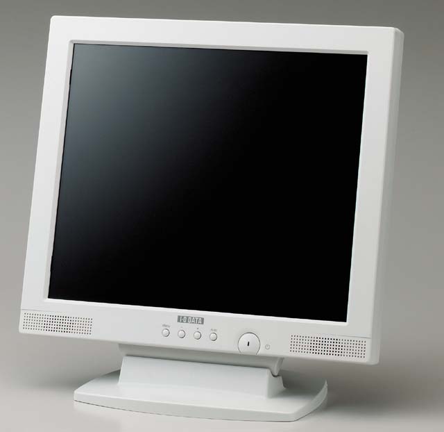
Now IODATA make pretty good TFT LCD screens and I love this one to bits, although it is rather bland to look at compared to the PC case, So I decided to design the new monitor housing around a Lexan frame with brushed aluminium plate for the buttons and LED’s, the same kind of style as the pump monitor that is on the case. I will use the same kind of Alan bolts that I have used while building the pc case along with moding the actual sub-frame of the of the LCD. Also I will either modify the original stand for the LCD or a swing arm that I have lying around.
TFT LCD Monitor Modification
Well as this is a total system modification I can’t let my stock LCD monitor go without at least seeing a screwdriver…. Actually this will be the 3rd time this monitor has been stripped and modified but the previous times it has only been for a re-spray.
Objective
Well as you spend almost most of your time looking at the monitor of your system I decided that I needed something more stylish than the original stock monitor.
Now IODATA make pretty good TFT LCD screens and I love this one to bits, although it is rather bland to look at compared to the PC case, So I decided to design the new monitor housing around a Lexan frame with brushed aluminium plate for the buttons and LED’s, the same kind of style as the pump monitor that is on the case. I will use the same kind of Alan bolts that I have used while building the pc case along with moding the actual sub-frame of the of the LCD. Also I will either modify the original stand for the LCD or a swing arm that I have lying around.
WARNING MODIFICATION OF ANY MONITOR IS DANGEROUS AND MAY RESULT IN INJURY OR DEATH. THIS THREAD IS IN NO WAY ENDORSING TAMPERING OR MODIFYING YOUR MONITOR AND ANYONE DECIDING TO DO SO, DOES AT THEIR OWN RISK.
Method
The first thing to do is unplug the monitor and let it sit for a couple of days to de-charge I left mine 3 days but I know that they have been known to keep a charge for up to 2 weeks, so if your not sure either don’t modify it or leave it longer. As you can see the sub-frame is fantastic and it makes you wonder why they covered it with that horrible shell! (Possibly to do with electric shocks and law suits?)

Now the shells off the 1st thing I did was to remove the retaining screws and replace them with the Alan bolt version, I had 4 laying around so it was a quick job to get a feel of the project and where it is going to go.

I also decided to clean it up a bit by removing the things that I wouldn’t be needing…. Like the built in speakers.

I have had this monitor about a year now and I have never used the speakers so out they come. Now if there is one thing I love, it’s good engineering the speakers were very easy to remove as they are connected to the monitor via Molex connectors that just plug in.

So by tracing it back to the controller PCB and then to where it connects to the Jack, I was able to remove them within 5 minutes with no fuss!

As you can see the way the sub-frame is put together makes it ideal for converting. The whole finish to the sub-frame is very clean and well made.

The first part of this mod will be the switches as I already know what I will be doing to this and how I want it to look so tomorrow I will be going down to the local hardware shop to buy more bolts and some sheet steal or aluminium.
Method
The first thing to do is unplug the monitor and let it sit for a couple of days to de-charge I left mine 3 days but I know that they have been known to keep a charge for up to 2 weeks, so if your not sure either don’t modify it or leave it longer. As you can see the sub-frame is fantastic and it makes you wonder why they covered it with that horrible shell! (Possibly to do with electric shocks and law suits?)
Now the shells off the 1st thing I did was to remove the retaining screws and replace them with the Alan bolt version, I had 4 laying around so it was a quick job to get a feel of the project and where it is going to go.
I also decided to clean it up a bit by removing the things that I wouldn’t be needing…. Like the built in speakers.
I have had this monitor about a year now and I have never used the speakers so out they come. Now if there is one thing I love, it’s good engineering the speakers were very easy to remove as they are connected to the monitor via Molex connectors that just plug in.
So by tracing it back to the controller PCB and then to where it connects to the Jack, I was able to remove them within 5 minutes with no fuss!
As you can see the way the sub-frame is put together makes it ideal for converting. The whole finish to the sub-frame is very clean and well made.
The first part of this mod will be the switches as I already know what I will be doing to this and how I want it to look so tomorrow I will be going down to the local hardware shop to buy more bolts and some sheet steal or aluminium.
As I said in the previous post the first step of this will be to modify the button panel, again this is on a type of IDE cable that easily detaches from the monitor so in doing so made the next part a whole lot easier for me.

I purchased aluminium in the end, several reasons why, it matches the case, doesn’t rust and is easy to fabricate into the finished product. I cut the panel bigger than the actual unit as the mounting holes are off on one side so by making the front plate longer it enabled me to balance the look of the button plate.

The next step was to file down the LED on the front. The reason for this is because it softens the light emitted and also so it doesn’t stick out of the front plate. I also filed out the mounting hole as I wished to use 4mm bolts rather than 3 as the head on the 4mm is bigger which gives a nicer finish to the look.

The LED now protrudes by about 1mm which is perfect for the later part of this mod.
Once that was done I marked out where the mounting screws would go and also the LED as these where the three main alignment points and getting those wrong would require me to start again from a fresh piece of metal.

I managed to align all three perfectly, measure and marking is critical for this kind of mod as if you rush it and get the mark even 0.5mm out then the buttons won’t fit. Once they where done I marked out the placement of the buttons and then punch marked them for the drill. (I always use a punch mark as it stops the drill from slipping).

Then here was the tricky part… I don’t have a bench drill and I wanted to drill 0.5 mm into the plate where the button holes are to create an edge around the hole making it easier to press the buttons. Doing this by hand was hard but I managed to get a good finish, although a drill press is high on my list of tools to get…. I might see if they do an adapter for standard drills!

Sorry for the poor images above as they where taken at 11pm and i was to tired to mess around with the camera.
I purchased aluminium in the end, several reasons why, it matches the case, doesn’t rust and is easy to fabricate into the finished product. I cut the panel bigger than the actual unit as the mounting holes are off on one side so by making the front plate longer it enabled me to balance the look of the button plate.
The next step was to file down the LED on the front. The reason for this is because it softens the light emitted and also so it doesn’t stick out of the front plate. I also filed out the mounting hole as I wished to use 4mm bolts rather than 3 as the head on the 4mm is bigger which gives a nicer finish to the look.
The LED now protrudes by about 1mm which is perfect for the later part of this mod.
Once that was done I marked out where the mounting screws would go and also the LED as these where the three main alignment points and getting those wrong would require me to start again from a fresh piece of metal.
I managed to align all three perfectly, measure and marking is critical for this kind of mod as if you rush it and get the mark even 0.5mm out then the buttons won’t fit. Once they where done I marked out the placement of the buttons and then punch marked them for the drill. (I always use a punch mark as it stops the drill from slipping).
Then here was the tricky part… I don’t have a bench drill and I wanted to drill 0.5 mm into the plate where the button holes are to create an edge around the hole making it easier to press the buttons. Doing this by hand was hard but I managed to get a good finish, although a drill press is high on my list of tools to get…. I might see if they do an adapter for standard drills!
Sorry for the poor images above as they where taken at 11pm and i was to tired to mess around with the camera.
The final part was to file the corners round and to sand it down, to do this I used 800 grit up to 2000 grit, I then used the Holts abrasive polish to get the shine finish. After 10 minutes of elbow grease I had the finish I wanted and then assembled the front button panel.

Now that the actual plate is finished for the button panel I’m not sure where to go from here. I have two designs in mind the 1st is to leave it be now and have the bare metal for the button plate and then do something with the actual monitor frame or the 2nd idea is to place an acrylic plate over the top it just like the drive bays in the PC.
I’m not asking for ideas here but merely sharing mine with you so you can get a feel of how this project develops!
I had some free time this evening so i started to mark out the acrylic sheet for the monitor frame. I spent a good 2 hours getting it perfect ready for cutting as it needs to be 100% accurate as any slight defect will really show… and I really don’t want to have to sit In front of a monitor that I don’t like the look of!

I will need to cut the middle out of this sheet but I’m really not sure how to do it … Some people complain about Dremel melting the plastic along the cut and I really don’t want any discolouration and the cutting toll I use for cutting acrylic ….well I would like to keep my thumbs this time….. So what else could I use?
I have a Black & Decker “Zip Saw” and I was wonder if it could do the job?

The full specs can be found Here
Any advice is welcome….although I will be trying it out on a test piece 1st!
I will need to cut the middle out of this sheet but I’m really not sure how to do it … Some people complain about Dremel melting the plastic along the cut and I really don’t want any discolouration and the cutting toll I use for cutting acrylic ….well I would like to keep my thumbs this time….. So what else could I use?
I have a Black & Decker “Zip Saw” and I was wonder if it could do the job?
The full specs can be found Here
Any advice is welcome….although I will be trying it out on a test piece 1st!
TFT LCD Monitor Modification
Method
After along period of measuring and marking out of the acrylic I decided to move across to Polycarbonate as it’s easier to fabricate.
Fortunately I had all the measurements already written out so it was just a case of getting the set square, measure and marker out again.
Next was selecting the correct tools for the job, In this next picture it shows all the blades that came with the Black & Decker Zip Saw the top one is for plastics but on trying it out on the old piece of acrylic I found that it was not good and moved over to the metal cutting blades circled in red…..now these went through it like a hot knife through butter!

Then I clamped down the sheet ready for cutting, in thee image below you can see a metal bar running over the work, well this is actually 30.1mm off the line I want to cut as this is the exact distance between the straight edge of the tool to the blade so that bar is actually working as my guide, all I did was clamp it down using two D-clamps and it worked perfectly as my guide resulting in perfectly straight lines!

I used this technique on every line to be cut including the shorter ones…. It took a little time but I wanted a perfect finish so I took my time. Here is a closer view of the guide and the finished cut.

It was painfully slow having to clamp and unclamp the work every time I made a cut but the results where perfect. I actually used 3 test pieces before working on the final piece just so I could get the technique right and also see which blades where best for the job and the RPM of the saw. But as I said the finished piece was worth the effort.

By the time this piece had been done was very confident with my technique and also the straight edge guide I had devised but when It came to the inside cuts I went back to the test piece to see if that same technique would work. Fortunately it did and all I found I had to do was make sure it was all clamped down securely so that it wouldn’t vibrate while cutting. You can see from this image how it is all clamped down.

I drilled out each corner enough to fit the blade through and then cut down to the line and then reversed the saw and worked back towards the hole. If you look closely you can see where the cut lines are and how the reverse cut goes past the hole to make the straight inside line.
Method
After along period of measuring and marking out of the acrylic I decided to move across to Polycarbonate as it’s easier to fabricate.
Fortunately I had all the measurements already written out so it was just a case of getting the set square, measure and marker out again.
Next was selecting the correct tools for the job, In this next picture it shows all the blades that came with the Black & Decker Zip Saw the top one is for plastics but on trying it out on the old piece of acrylic I found that it was not good and moved over to the metal cutting blades circled in red…..now these went through it like a hot knife through butter!
Then I clamped down the sheet ready for cutting, in thee image below you can see a metal bar running over the work, well this is actually 30.1mm off the line I want to cut as this is the exact distance between the straight edge of the tool to the blade so that bar is actually working as my guide, all I did was clamp it down using two D-clamps and it worked perfectly as my guide resulting in perfectly straight lines!
I used this technique on every line to be cut including the shorter ones…. It took a little time but I wanted a perfect finish so I took my time. Here is a closer view of the guide and the finished cut.
It was painfully slow having to clamp and unclamp the work every time I made a cut but the results where perfect. I actually used 3 test pieces before working on the final piece just so I could get the technique right and also see which blades where best for the job and the RPM of the saw. But as I said the finished piece was worth the effort.
By the time this piece had been done was very confident with my technique and also the straight edge guide I had devised but when It came to the inside cuts I went back to the test piece to see if that same technique would work. Fortunately it did and all I found I had to do was make sure it was all clamped down securely so that it wouldn’t vibrate while cutting. You can see from this image how it is all clamped down.
I drilled out each corner enough to fit the blade through and then cut down to the line and then reversed the saw and worked back towards the hole. If you look closely you can see where the cut lines are and how the reverse cut goes past the hole to make the straight inside line.
Once that was done I was left with the ruff cut frame ready to be sanded and marked out for drilling.

Due to this method of cutting it left one or two of the edges a little bowed, so the next job was to file them down to perfectly straight lines. For this I used metal rulers on both sides of the polycarbonate sheet placed precisely at the correct height and then filed away the raised area, I did this on all the internal edges even on the two sides that looked perfect as they also had very low raises to them which would become noticeable while looking at the monitor for long periods of time so they all had to be perfect.

Once all the edges where filed down to remove the burrs it was time to mark out the sheet for drilling, now unlike acrylic this stuff is really easy to drill. The only time I had problems was when I had to drill two holes that where 12mm wide and the drill got clogged up and I had to cut away the plastic from the drill and continue drilling after that.
The drill holes had to be perfectly placed for affixing otherwise they wouldn’t align correctly with the monitor. Also making slightly larger holes to allow travel wasn’t an option either as I wanted to mask the bolt shafts with brushed steel tubing to give a professional look to the finished product.

The next job was to cut the bolt covering, 1st I cut them all to 20mm lengths as this was the depth of the monitor 2nd I marked off the lengths between the polycarbonate sheet and the fixing mount on the monitor. Using a clamp to hold the tubing I cut the 20mm lengths to the required length.

Now cutting them from 20mm down to the required lengths was done for two reasons…. To get the correct lengths but also the actual cutting removed about 1mm which is the depth of the fixing brackets on the monitor so I only needed to measure 1 cut …it just saved time.

I then screwed them into the fixing brackets to make sure the fitted correctly and also to get a feel for how it would look once the polycarbonate sheet would look once it was complete.
Now the next job was to affix the 20x200mm LCD that used to be in the PC, I decided to remount it as I thought it was wasted in the drive bays as normally I have the door shut and it’s not convenient to bend over to look at the temps or other readouts while fragging away in BF:V or using other full screen apps! So it was time to move it.
Apparently this is the first time a LCD has been incorporated in to a monitor so I wanted to do the best job possible!
I drilled out the 12mm holes for the power and lighting switches, I decided to keep these as I realised that for a monitor mounted LCD these would be perfect as there would be times where the Blue LED’s would be a distraction and also the different readout cycling through…… so I could either turn off the lighting to the LCD or turning off the whole unit. As I said earlier the polycarbonate really didn’t like the 12mm drill bit and I had to work really slowly applying almost no pressure to the drill and also removing any burrs that crept up the drill bit.

Now I love these switches as they come with a great mounting clip and the finish is just so nice! I might have a look for different types the next time I’m over in Akihabara but to be honest I think these ones go perfectly with the style of the monitor.
Due to this method of cutting it left one or two of the edges a little bowed, so the next job was to file them down to perfectly straight lines. For this I used metal rulers on both sides of the polycarbonate sheet placed precisely at the correct height and then filed away the raised area, I did this on all the internal edges even on the two sides that looked perfect as they also had very low raises to them which would become noticeable while looking at the monitor for long periods of time so they all had to be perfect.
Once all the edges where filed down to remove the burrs it was time to mark out the sheet for drilling, now unlike acrylic this stuff is really easy to drill. The only time I had problems was when I had to drill two holes that where 12mm wide and the drill got clogged up and I had to cut away the plastic from the drill and continue drilling after that.
The drill holes had to be perfectly placed for affixing otherwise they wouldn’t align correctly with the monitor. Also making slightly larger holes to allow travel wasn’t an option either as I wanted to mask the bolt shafts with brushed steel tubing to give a professional look to the finished product.
The next job was to cut the bolt covering, 1st I cut them all to 20mm lengths as this was the depth of the monitor 2nd I marked off the lengths between the polycarbonate sheet and the fixing mount on the monitor. Using a clamp to hold the tubing I cut the 20mm lengths to the required length.
Now cutting them from 20mm down to the required lengths was done for two reasons…. To get the correct lengths but also the actual cutting removed about 1mm which is the depth of the fixing brackets on the monitor so I only needed to measure 1 cut …it just saved time.
I then screwed them into the fixing brackets to make sure the fitted correctly and also to get a feel for how it would look once the polycarbonate sheet would look once it was complete.
Now the next job was to affix the 20x200mm LCD that used to be in the PC, I decided to remount it as I thought it was wasted in the drive bays as normally I have the door shut and it’s not convenient to bend over to look at the temps or other readouts while fragging away in BF:V or using other full screen apps! So it was time to move it.
Apparently this is the first time a LCD has been incorporated in to a monitor so I wanted to do the best job possible!
I drilled out the 12mm holes for the power and lighting switches, I decided to keep these as I realised that for a monitor mounted LCD these would be perfect as there would be times where the Blue LED’s would be a distraction and also the different readout cycling through…… so I could either turn off the lighting to the LCD or turning off the whole unit. As I said earlier the polycarbonate really didn’t like the 12mm drill bit and I had to work really slowly applying almost no pressure to the drill and also removing any burrs that crept up the drill bit.
Now I love these switches as they come with a great mounting clip and the finish is just so nice! I might have a look for different types the next time I’m over in Akihabara but to be honest I think these ones go perfectly with the style of the monitor.
Again I used the same brushed tubing to cover the bolts for the LCD this time I got thinner ones as the bolts where only 0.2mm as the depth between the PCB and the polycarbonate was only 8mm I decided to take these ones down with a file.

Now these tubes really are needed for the LCD as if I affixed it directly to the polycarbonate the PCB flexes and pushes the second PCB attached to it out by about 3mm. Again it was also in keeping with the whole project so I thought it best to keep them in place and to get the right diameter to the bolts.


The next thing to do was to plug the LCD into the Com port to make sure that it was still working and reporting back correctly.(There is nothing worse than spending time getting something perfect only to find out it doesn¡¦t work any more!) I also wanted to make sure that the LCD didn¡¦t interfere with the monitor in anyway and vice versa, fortunately this wasn¡¦t the case and the LCD fired up perfectly the First time!

The final job was to remove everything again and to remove the protective plastic film covering both sides of the polycarbonate sheet, You can¡¦t believe how tempted I was during the fabrication process to remove it just to see how it all looked but I resisted and I¡¦m glad I did as I can now see it in all it¡¦s glory.

Conclusion
In some of the pictures the LCD seems lopsided, this was caused by one of the tubes being 1mm to long and causing the LCD not to sit correctly. This has now been rectified.
As I stated I used three sheets of polycarbonate 1 being the finished product that you see throughout the walkthrough and the other two for cutting practice and also technique practice. Actually I have a spare window frame for this monitor as the 2nd test sheet came out perfectly apart from a few marks left from the clamps, as I didn¡¦t protect the sheet when clamping it down. Which was good as it made me extra careful when doing the actual final product.
The next problem I have is that the connection lead for the LCD was actually run under the motherboard so to get it out I¡¦m going to have to strip the PC down again to remove the cable! Not really a problem, I just wish I had thought of putting the LCD in the monitor before hand!
Where will it go from here? Well there are two possibilities the first is to give the polycarbonate a back panel to do this I will use the side panel from the PC as once the etching arrives it will be a spare so I could cut the side panel so that it 100% matches the PC casing, although this will lose the skeleton look of the monitor. The second option is¡Kwell your looking at it, to leave the monitor just how it is.
Now these tubes really are needed for the LCD as if I affixed it directly to the polycarbonate the PCB flexes and pushes the second PCB attached to it out by about 3mm. Again it was also in keeping with the whole project so I thought it best to keep them in place and to get the right diameter to the bolts.
The next thing to do was to plug the LCD into the Com port to make sure that it was still working and reporting back correctly.(There is nothing worse than spending time getting something perfect only to find out it doesn¡¦t work any more!) I also wanted to make sure that the LCD didn¡¦t interfere with the monitor in anyway and vice versa, fortunately this wasn¡¦t the case and the LCD fired up perfectly the First time!
The final job was to remove everything again and to remove the protective plastic film covering both sides of the polycarbonate sheet, You can¡¦t believe how tempted I was during the fabrication process to remove it just to see how it all looked but I resisted and I¡¦m glad I did as I can now see it in all it¡¦s glory.
Conclusion
In some of the pictures the LCD seems lopsided, this was caused by one of the tubes being 1mm to long and causing the LCD not to sit correctly. This has now been rectified.
As I stated I used three sheets of polycarbonate 1 being the finished product that you see throughout the walkthrough and the other two for cutting practice and also technique practice. Actually I have a spare window frame for this monitor as the 2nd test sheet came out perfectly apart from a few marks left from the clamps, as I didn¡¦t protect the sheet when clamping it down. Which was good as it made me extra careful when doing the actual final product.
The next problem I have is that the connection lead for the LCD was actually run under the motherboard so to get it out I¡¦m going to have to strip the PC down again to remove the cable!
Not really a problem, I just wish I had thought of putting the LCD in the monitor before hand! Where will it go from here? Well there are two possibilities the first is to give the polycarbonate a back panel to do this I will use the side panel from the PC as once the etching arrives it will be a spare so I could cut the side panel so that it 100% matches the PC casing, although this will lose the skeleton look of the monitor. The second option is¡Kwell your looking at it, to leave the monitor just how it is.
TFT LCD Monitor Modification Part 2
Monitor Stand and Fixings
The second step was to modify the stand on which the monitor would sit, I decided to make the link between the monitor and the actual PC here as I really like the skeleton look of the monitor but also I really wanted to have it themed like the PC case. I decided that I would construct the base in exactly the same way as I had the stealthed drive bays.
As I had a lot of the polycarbonate left over (The middles of the Monitor Frame) I decided to use these instead of the fresh pieces I have. I marked out the shape of the stands base and also where the fixing bolts would go.

Once this was done I drilled all the mounting points and also cut out the central strip where the stand joins the actual monitor. Now the original gap was around 10mm but I wanted a cleaner finish so reduced the gap to 5mm.

The next part was the brushed aluminium sheet now I picked up a 2mm thick sheet of this very cheaply but the finish was actually a polished finish rather than a brushed finish which is the finish to the actual PC case so I had to work on that once the cuts and drilling had been completed. To get the brushed effect I used 800 Grit sand-papers and worked in one direction only I then moved up to 1000 grit sand paper and then used a special sponge that we use in our kitchen to polish the steel work surfaces up. This created the perfect brushed effect that the case has.

After this had been done I attached all the pieces together to make sure none of the layers stuck out, IN the next image you can see that the aluminium sheet sticks out by 2mm in some places so I took the file to all the edges to make sure everything was level and matched correctly.

Once the base was assembled and all the layers filed down to match I flipped the stand over. As you can see the bolts on the other side protrude rather far so again it was time for the trusty file to take them down.

Once they had all been filed down it was time to cover them, I went to the local hardware store and picked up some rubber non-slip pads that you put under TV’s and other hardware. I used the 10mm drill bit to take the middle out of them so they would fit perfectly over the bolts.

Monitor Stand and Fixings
The second step was to modify the stand on which the monitor would sit, I decided to make the link between the monitor and the actual PC here as I really like the skeleton look of the monitor but also I really wanted to have it themed like the PC case. I decided that I would construct the base in exactly the same way as I had the stealthed drive bays.
As I had a lot of the polycarbonate left over (The middles of the Monitor Frame) I decided to use these instead of the fresh pieces I have. I marked out the shape of the stands base and also where the fixing bolts would go.
Once this was done I drilled all the mounting points and also cut out the central strip where the stand joins the actual monitor. Now the original gap was around 10mm but I wanted a cleaner finish so reduced the gap to 5mm.
The next part was the brushed aluminium sheet now I picked up a 2mm thick sheet of this very cheaply but the finish was actually a polished finish rather than a brushed finish which is the finish to the actual PC case so I had to work on that once the cuts and drilling had been completed. To get the brushed effect I used 800 Grit sand-papers and worked in one direction only I then moved up to 1000 grit sand paper and then used a special sponge that we use in our kitchen to polish the steel work surfaces up. This created the perfect brushed effect that the case has.
After this had been done I attached all the pieces together to make sure none of the layers stuck out, IN the next image you can see that the aluminium sheet sticks out by 2mm in some places so I took the file to all the edges to make sure everything was level and matched correctly.
Once the base was assembled and all the layers filed down to match I flipped the stand over. As you can see the bolts on the other side protrude rather far so again it was time for the trusty file to take them down.
Once they had all been filed down it was time to cover them, I went to the local hardware store and picked up some rubber non-slip pads that you put under TV’s and other hardware. I used the 10mm drill bit to take the middle out of them so they would fit perfectly over the bolts.
So now the stand is going nowhere and I don’t have to worry about those bolts scratching up my desk. Now you’re probably wondering about the fan grills and what happened to the redundant 40mm fan grill I had made for the Northbridge cooler.

Well here she is, I loved this little fan grill and I really didn’t want it going to waste so I decided to incorporate into the monitor design. Well this is where I decided to place it, smack bang in the middle of the stand base.

Now it was time to mate the stand with the monitor. As I have this Alan key bolt theme going I decided to change a lot of the fixing bolts as well including those to mount the monitor, as you would agree it’s the small things like this that put the icing on the cake.

Well here she is, I loved this little fan grill and I really didn’t want it going to waste so I decided to incorporate into the monitor design. Well this is where I decided to place it, smack bang in the middle of the stand base.
Now it was time to mate the stand with the monitor. As I have this Alan key bolt theme going I decided to change a lot of the fixing bolts as well including those to mount the monitor, as you would agree it’s the small things like this that put the icing on the cake.


-