 26.04.2024, 16:18
 Sprache ändern
 Registrieren
 Anmelden
Sie sind nicht angemeldet.
Lieber Besucher, herzlich willkommen bei: Aqua Computer Forum. Falls dies Ihr erster Besuch auf dieser Seite ist, lesen Sie sich bitte die Hilfe durch. Dort wird Ihnen die Bedienung dieser Seite näher erläutert. Darüber hinaus sollten Sie sich registrieren, um alle Funktionen dieser Seite nutzen zu können. Benutzen Sie das Registrierungsformular, um sich zu registrieren oder informieren Sie sich ausführlich über den Registrierungsvorgang. Falls Sie sich bereits zu einem früheren Zeitpunkt registriert haben, können Sie sich hier anmelden.

DerrickD,
i couldn't resist a little peak at your pc, nice looking rig. i
think the main reason you are having problems getting it all
in your case, is that you are using 1/2" tubing.
using a 1/2" high flow system may give you a slight better
performace like 1-2 deg but a low flow system like push fit
connectors will allow you to cool more blocks. to get 3 loops
in your case using 1/2" tubing imo is gonna be impossible
without using lots of elbows and then you are gonna kill your
flow, which is not a good thing on a high flow system. where
as a low flow does not matter so much
hope im not babbling to much :
Zitat von »Ze@lot«
DerrickD,
i couldn't resist a little peak at your pc, nice looking rig. i
think the main reason you are having problems getting it all
in your case, is that you are using 1/2" tubing.
using a 1/2" high flow system may give you a slight better
performace like 1-2 deg but a low flow system like push fit
connectors will allow you to cool more blocks. to get 3 loops
in your case using 1/2" tubing imo is gonna be impossible
without using lots of elbows and then you are gonna kill your
flow, which is not a good thing on a high flow system. where
as a low flow does not matter so much
hope im not babbling to much :
ya I see what your talking about the video car block has 3 90s on it if I put some more thought in to it i can lose one of them im not to wraped up in that loop as i am in the cpu loop as far as flow and cooling, and i realy like working with the 1/2in line
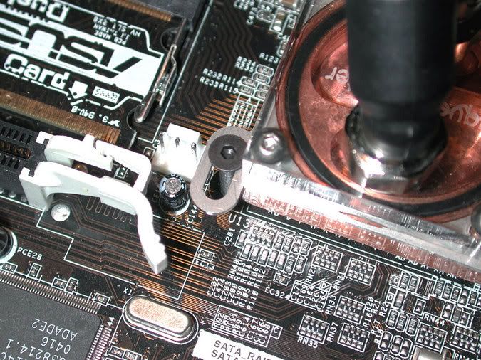
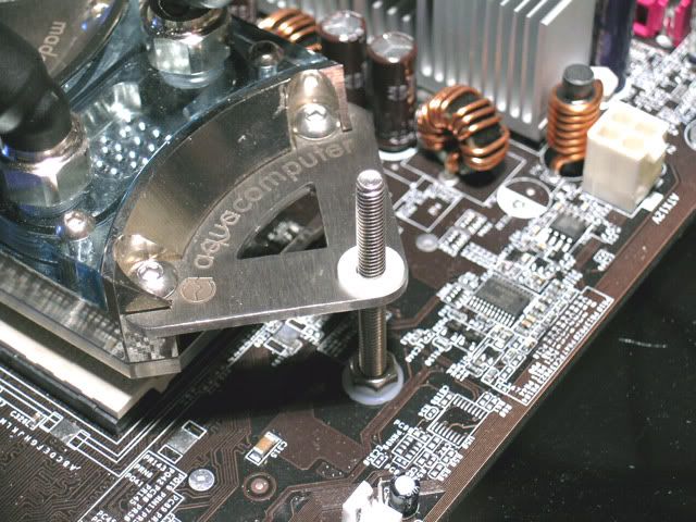
Have you had that problem mounting a TwinPlex with the factory screws where the block moves around easily due to the small diameter of the screw in the slot of the mounting screen? This really bugged me so I tried many a different solution. The winner was by using a M3 x 20mm flat head socket cap screw and a nylon flat washer under a 3mm nut on the back side of the board. The flat head design makes it so there is no wiggle room in the mounting screen and it looks a lot cooler than those round head zinc plated screws AC supplies. Got lucky and found the screw and nut in black. 
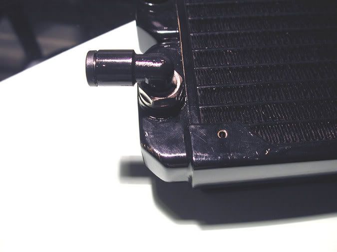
Also decided I didn't like the way I had the rad in the middle compartment as one was metal and one was black. So paint it! ;D
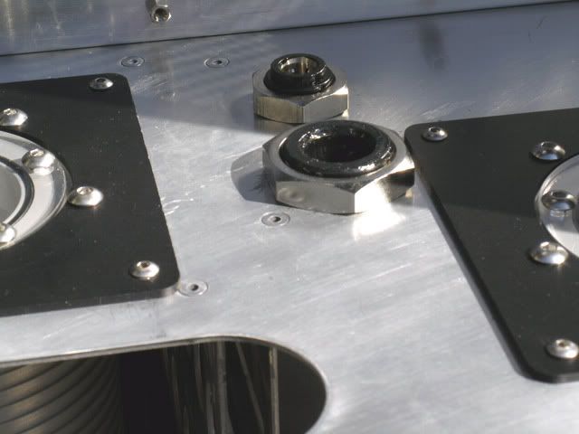
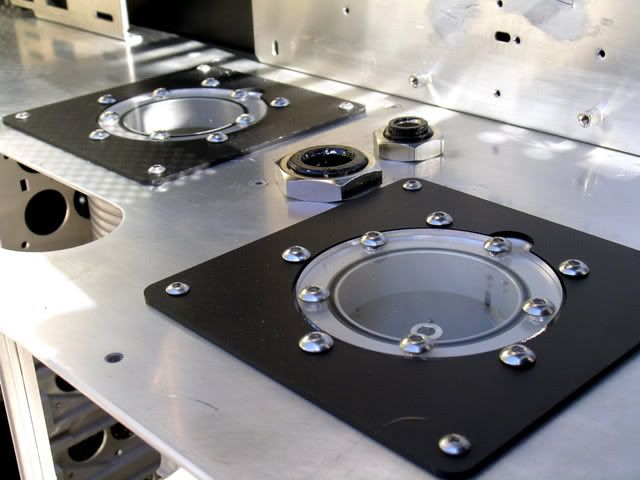
Decided to paint some other fittings too. Here is my 6mm bulkhead fitting I got from McMaster-Carr. Came 100% nickel plated so I decided that a little black might look nice here as well.
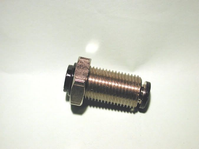
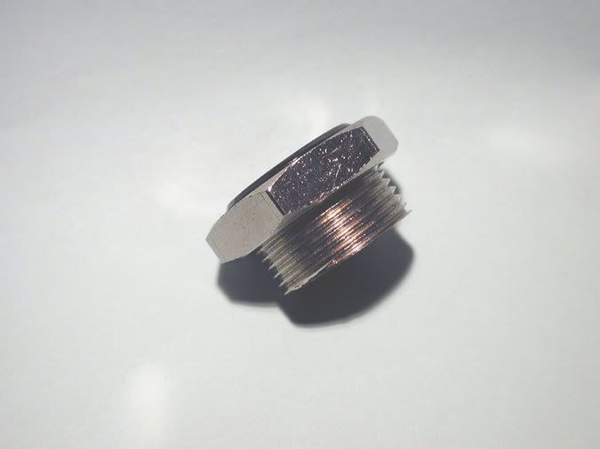
A ways back you saw that gigantic fitting in my fittings box? That was a 3/8" bulkhead I also got from McMaster-Carr. Well I took out the tube holding collets and cut it in half with a hacksaw. This turned it into a nice little bulkhead fitting to run my ATX power loom through the case bulkhead floor. Painted the inside and both ends and it will be ready to go in the case once the paint dries and I can add a second coat.
Side view:
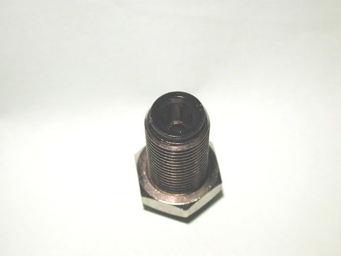
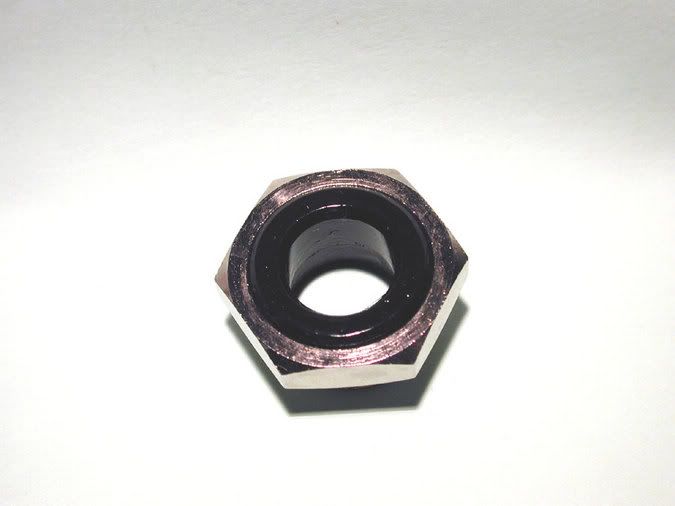
Top view:
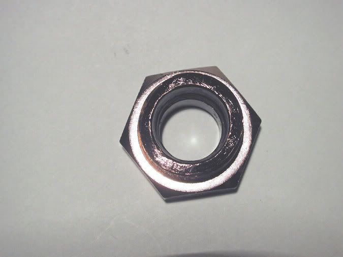
Bottom view:
Also decided I didn't like the way I had the rad in the middle compartment as one was metal and one was black. So paint it! ;D
Decided to paint some other fittings too. Here is my 6mm bulkhead fitting I got from McMaster-Carr. Came 100% nickel plated so I decided that a little black might look nice here as well.
A ways back you saw that gigantic fitting in my fittings box? That was a 3/8" bulkhead I also got from McMaster-Carr. Well I took out the tube holding collets and cut it in half with a hacksaw. This turned it into a nice little bulkhead fitting to run my ATX power loom through the case bulkhead floor. Painted the inside and both ends and it will be ready to go in the case once the paint dries and I can add a second coat.
Side view:
Top view:
Bottom view:

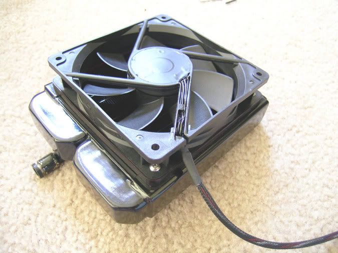
Got a little more work done. Finished up on my radiator/fan sub-assembly. The back radiator fan cable has a long way to go to the front of the case where the Aquaero sits. The cable is about 5 feet long as it has to go the long way around. :o
You might not notice it, but their is a Vantec 120mm fan gasket between the radiator and the fan. Suitably dyed in black of course.
Finally decided to give up on getting some clear acrylic on the side of my waterblocks. It just was to much trouble. So here it is with some special English wax on it (hot tip from my guy who details my car). I guess we will see in a few months how well this holds up. As you can see I spent some time getting a very nice *bling* finish on the outside surfaces. It was finished up with 3,000 grit and the bottom I did to about 2,000 grit. Used Ceramique to mount and checked the imprint and it was perfect. I ditched the Aqua Computer fittings in favor of Legris fittings as they have a nicer look and bigger holes (more flow).
Notice the nice finish on the Twinplex mounting screen? Well the sandpaper was there so I decided it couldn't hurt to polish it up a bit.
Tomorrow I will be mounting the back radiator grill and routing the wires up to the Aquaero. Also hope to finish up on the SLI power and 4 pin MB power connector looms as well.
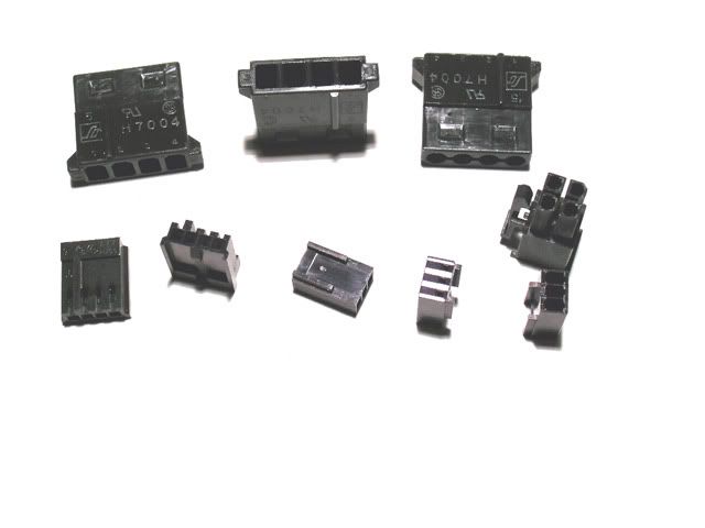
Good work takes a while, but this mod seems to be dragging on and on as I have been working on this since February and I'm just getting ready to have the side panel cut. Just ordered some new stuff from Performance PCS that should be here next week so I can finish my wiring. Needed some more black Molex connectors and of course for some real *bling bling* gold plated Molex pins. Building this in a manner that is sleek and good looking is much like building a prototype car as everything is hand done and fitted numerous times. I can't even remember how many times that MB has been in and out of that case. 
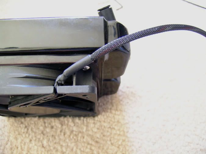
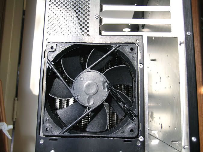
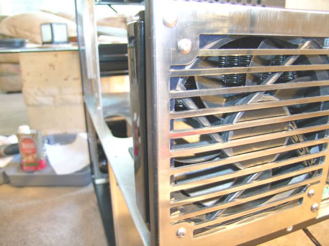
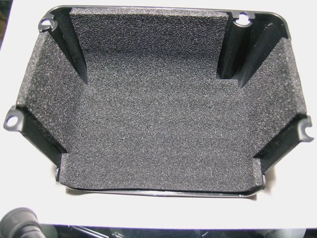
For example a while back some people thought I had cut a pretty jagged hole for the rear fan. Really there was a method to my madness as you can see from the following pic. I roughed it in with a jig saw and cut it to fit the fan. Suggestion: Don't buy any Acoustifan Dustproof's unless you want to do the same. I complained to Sharka about this fan being made from an out-of-spec injection molding die and the importer Quiet PC says they are all like this and tough tootsies. At least Sharka offered to exchange them, but by the time I realized what the problem was I had already cut the fan wires and painted them.
Looks like some new Dremel tool time as my fan gasket doesn't quite fit. I thought about leaving the fan gasket out on this side of the fan, but that is not possible. The thickness of the fan gasket is calculated into where the hole is for the 90 degree elbow. No fan gasket = no fit for the elbow. What happened to the days when I could get my hardware one day and have it completely built and programmed by the next day? :'(
Small update here though it took most of yesterday to get the grill and fan fitted to the back of the case. Had to get the Dremel tool out to open up the hole a bit as the fan to grill gasket wasn't clearing. Slight problem as well because my Dremel tool burned out the speed controller and either I get it off or 30,000 RPM :o so I went through a few tools.
I also took some time to sand the grill down to eliminate a few scratches and then decided a little polishing wouldn't hurt as well. This is the grill that I had milled so it would have a better fit than the stock one.
This is what I started out with and had to grind off some more clearance.
Here it shows what I had to go through to get this bolted up correctly. Essentially everytime I fitted this grill I have to move the fan back as far as possible, attach the grill to the fan, attach the 90 degree elbow, move the fan/grill/rad assembly forward so that I could screw down the four bolts that actually hold it to the case. As you can see I am exclusively using stainless steel button head socket cap screws. I also used nylock lock nuts so I don't have any problems once it is all screwed down. There are two 120mm fan gaskets used here. One on each side of the fan and as explained previously they are dyed black.
I tried to get a pic of the polished grill so you could see some reflections.
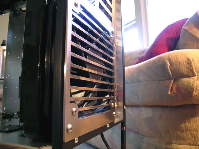
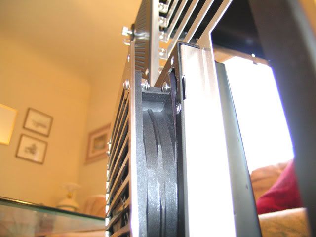
This pic shows how this grill looks when it is cut to the correct size. I tried to leave just a nice thin line of black case for that stellar look. ;D
Again just a hint of black case.
Here we are looking fron the top of the grill and it has the grill positioned so that it mates with the radius of the case.
Well that is it till tomorrow. Got the rest of my electrical stuff coming from Performance PCS so I will probably work on getting the third Aquatube and running some power wires tomorrow.
I also took some time to sand the grill down to eliminate a few scratches and then decided a little polishing wouldn't hurt as well. This is the grill that I had milled so it would have a better fit than the stock one.
This is what I started out with and had to grind off some more clearance.
Here it shows what I had to go through to get this bolted up correctly. Essentially everytime I fitted this grill I have to move the fan back as far as possible, attach the grill to the fan, attach the 90 degree elbow, move the fan/grill/rad assembly forward so that I could screw down the four bolts that actually hold it to the case. As you can see I am exclusively using stainless steel button head socket cap screws. I also used nylock lock nuts so I don't have any problems once it is all screwed down. There are two 120mm fan gaskets used here. One on each side of the fan and as explained previously they are dyed black.
I tried to get a pic of the polished grill so you could see some reflections.
This pic shows how this grill looks when it is cut to the correct size. I tried to leave just a nice thin line of black case for that stellar look. ;D
Again just a hint of black case.
Here we are looking fron the top of the grill and it has the grill positioned so that it mates with the radius of the case.
Well that is it till tomorrow. Got the rest of my electrical stuff coming from Performance PCS so I will probably work on getting the third Aquatube and running some power wires tomorrow.
nice work again TN, they do say its all in the detail ;D
what grade of wet & dry did you use tho on the grills ?
The devil is in the details is what they say.
I originally started out with 400 grit but it was to slow so i went to 220 grit. Problem is that the grill isn't flat so you have a couple of options. One you sand till the cows come home or two you get a buffing wheel. This one was done with sanding, but the top grill will be bolted to a 4" x 4" hunk of wood and go at it with a buffing wheel. It all depends on the part though as I am working currently on an Aquastream controller faceplate and it is probably better to sand it.
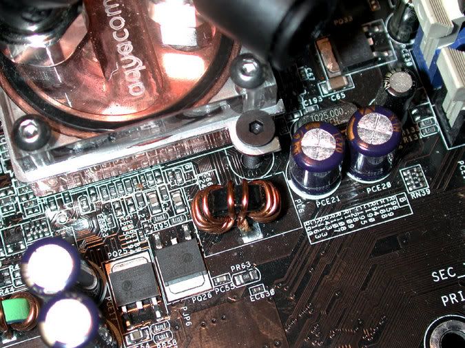
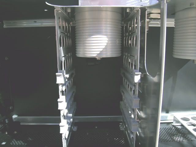
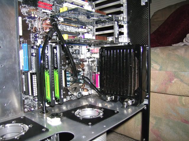
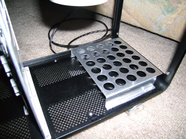
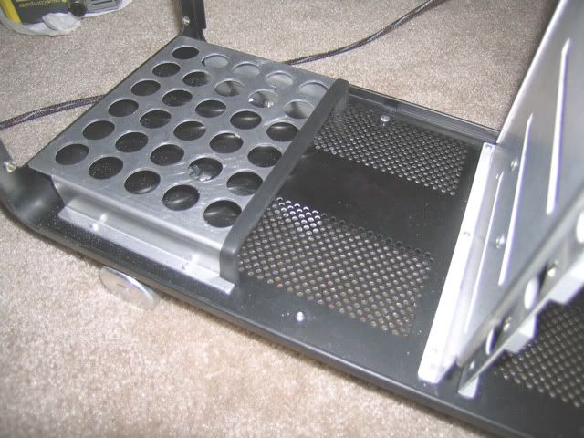
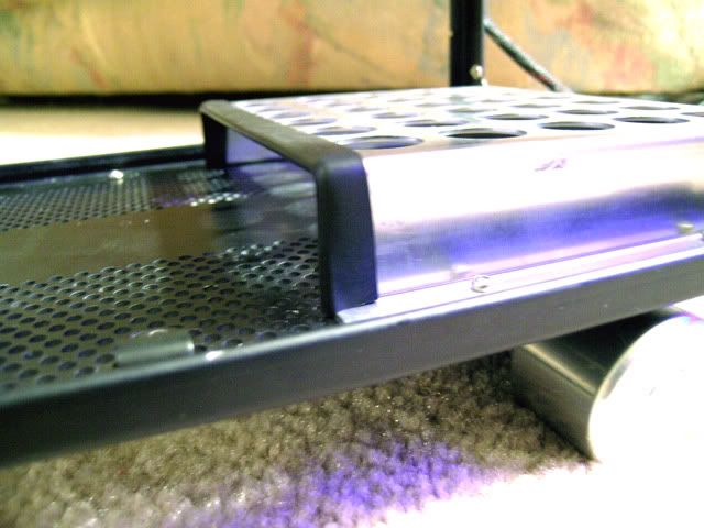
Little update today as I finished putting in my 3rd Aquatube which is for the HD loop. The original plans were for an Aquainlet with my Aquastream. After I set it in the case I decided that it just looked kind of out of place iff you know what I mean. Here is the hole I cut for the Aquatube. You can also see now the bushing I showed a while back painted and installed. The main ATX power loom will be going through here to the MB. The smaller part in the back is an 8mm nickel plated pushfit painted on the top.
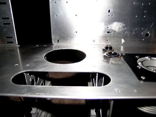
Here is looking to the back of the middle case as well. That big long cable you see in the bottom right is the fan cable that will go to the Aquaero in the front of the case.
Here is the Aquatube as you see it under the middle floor. I removed the top two HD rails to get the Aquatube in, which leaves me with three watercooled HD's for now.
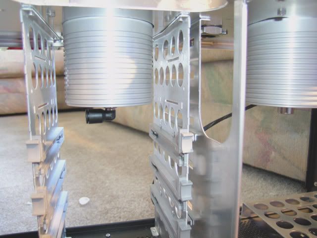
Here is with the Aquatube screwed down to the case. If you are an AC fan then you probably noticed that I deviated with the size of the screws that hold the mounting plate on. I just thought it looked too busy with all those 4mm screws on the face of the Aquatube. So to break up the monotony I decided to use 3mm screws instead. I think it gives it a much better look now.
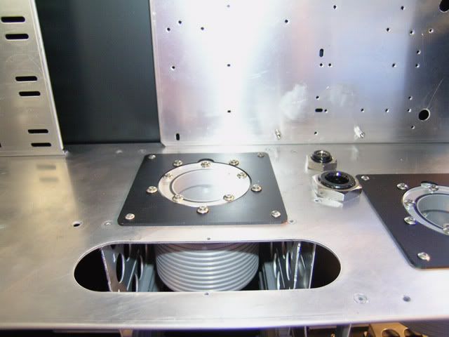
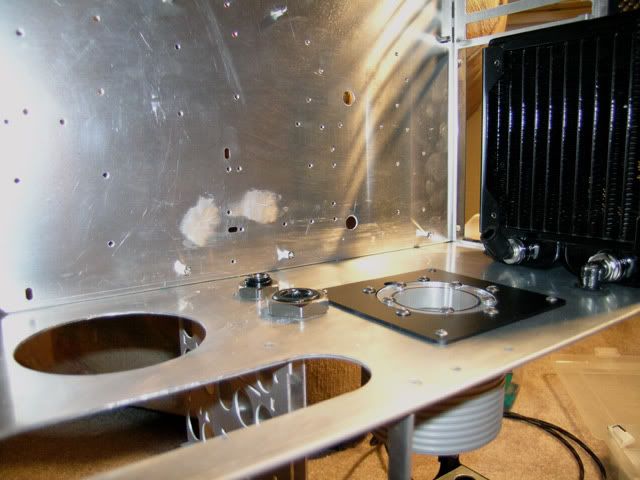
Here is a close-up of the bulkhead fittings. Debating whether to strip the paint off and sand the nickel plating off so I have a better surface to paint on.
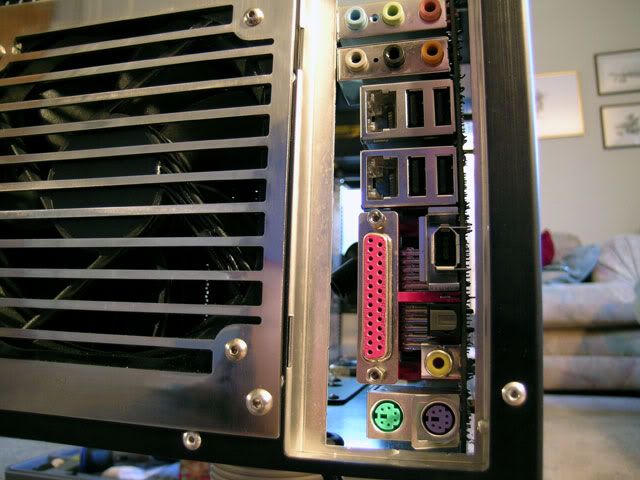
Here is a look from the back of the case.
With this pic I think you might begin to see why I choose black fittings and black tubing. There really is an 8mm 90 degree pushfit at the bottom of the Aquatube. ;D
Well that is it for now so see ya later alligator.
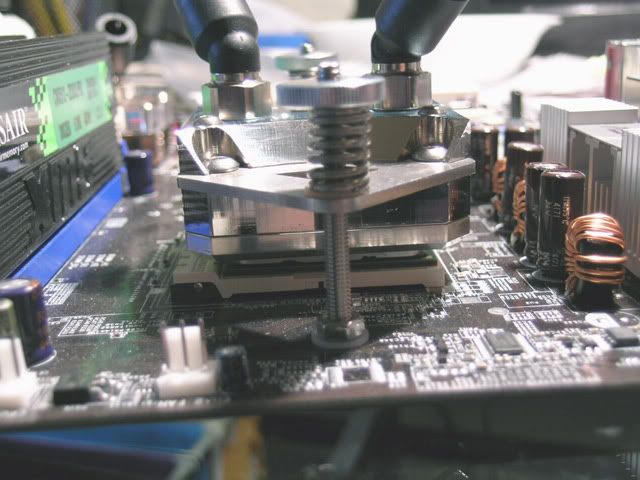
Well as it turns out my A.C. Ryan stuff shows up tomorrow from Performance PCS so I decided it was time to put the Silver Cuplex XT on the board. Tomorrow my black connectors and gold molex stuff goes in. Later tonight I will put it in the case. However, I often hear that people that read English have a hard time deciphering the German AC manuals so this set of pics is for you. As you probably noticed the stock screws on this cooler disappeared in favor of my stainless steel buttonheads.
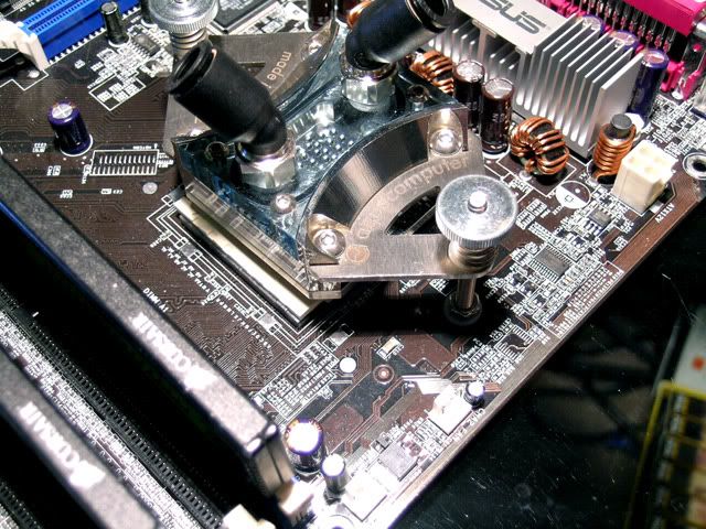
Here is the XT mounted loosely and shows the proper fastener sequence. If I ever take it off I think I will eliminate the plastic washer under the spring as it seems to hinder proper spring placement, but it also keeps the spring from digging into the mount and binding up so you pays your money and you take your chances. ;D
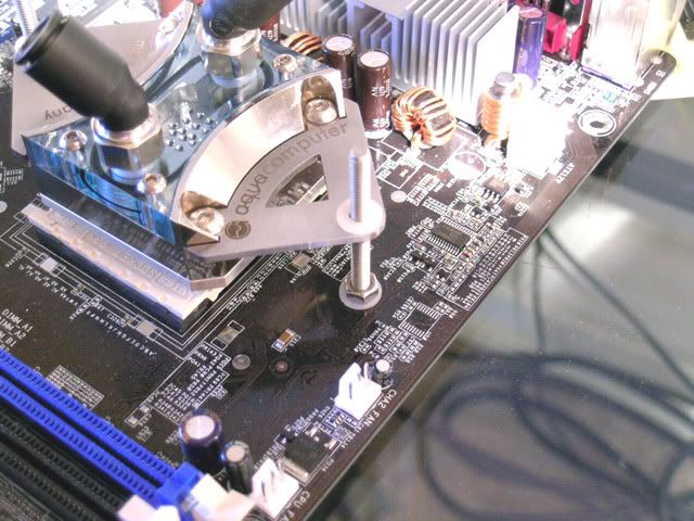
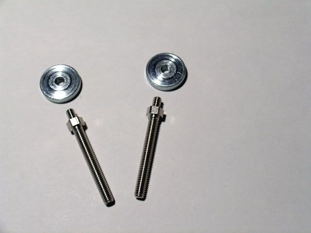
Here is the nut that goes on top of the spring and the studs that are included with the kit. I wanted to use the studs with my Asus A8N-SLI backing plate but they weren't long enough. So I used the included machine screws. I assumed that the part with the upraised area on the nuts was to go on the spring side.
Artic Silver 5 applied and springs are sitting on ready.
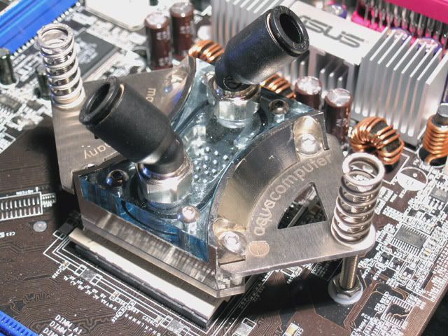
Here is the XT mounted and the nuts carefully tightened up. I used 1/4 turns alternating from side to side.
And last I have a side view for you. The instructions say that the springs should be compressed enough that a single sheet of paper can be slid between them.
That's it for now. Will try and get some more pics up later tonight with the MB permanently installed (I hope). :-/
Added:
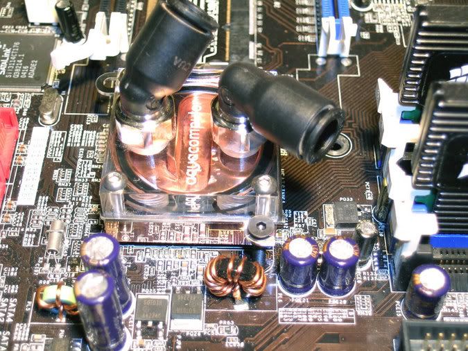
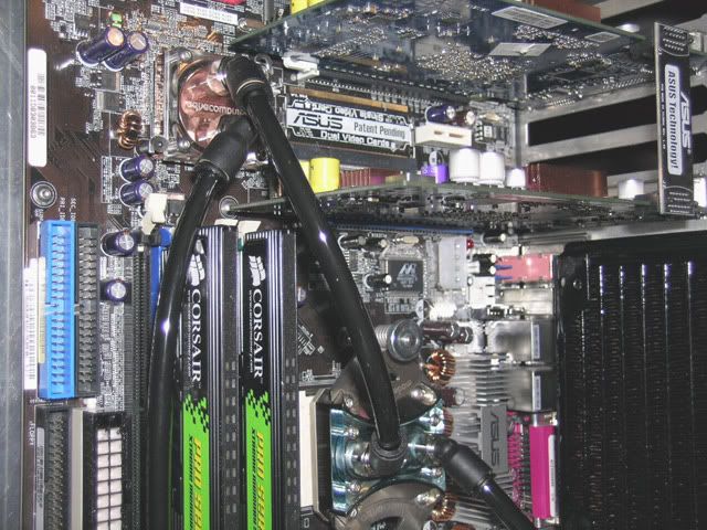
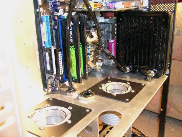
All right I promised you guys some pics of the MB installed tonight so here it is. No tubing in yet and the video cards were put in just for show as they are missing the waterblocks.
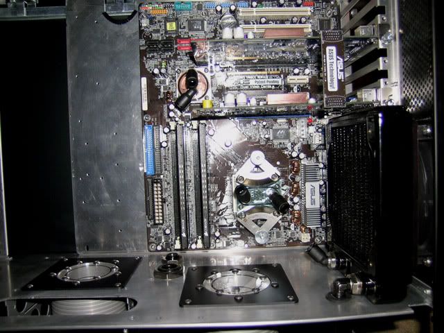
All right I took pity on R1ckCa1n and decided that I could at least put some tubing in. The water flows from the pump > radiator > Cuplex XT > Twinplex > Aquatube. When my stuff shows up from Performance PCS tomorrow I can put the PSU in and start the wiring job.
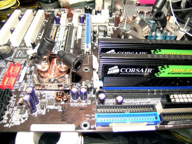
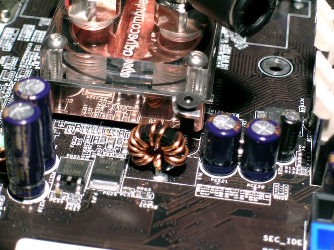
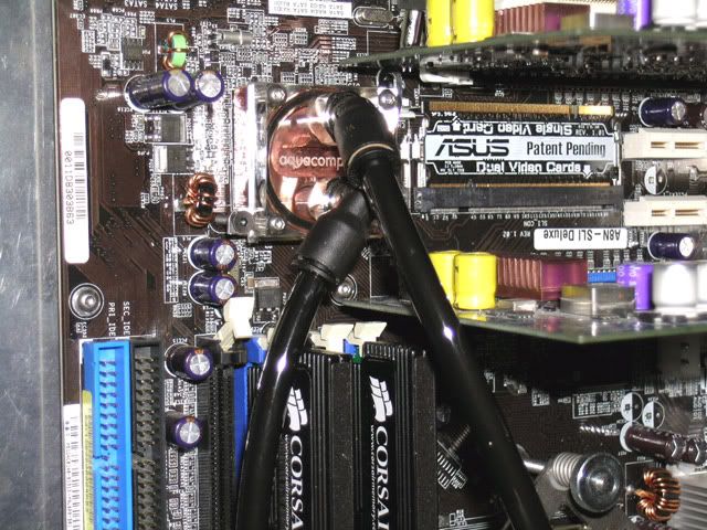
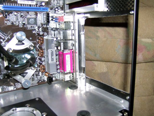
Looking from the front of the case. The original plan was to run the return line from the NB right between the memory modules as it seemed like a straight shot and would probably be near invisible. Then I got to be thinking of adding some longer video cards down the line and decided that would be a problem. So I decided to go outside the memory modules. Hopefully it will look okay...
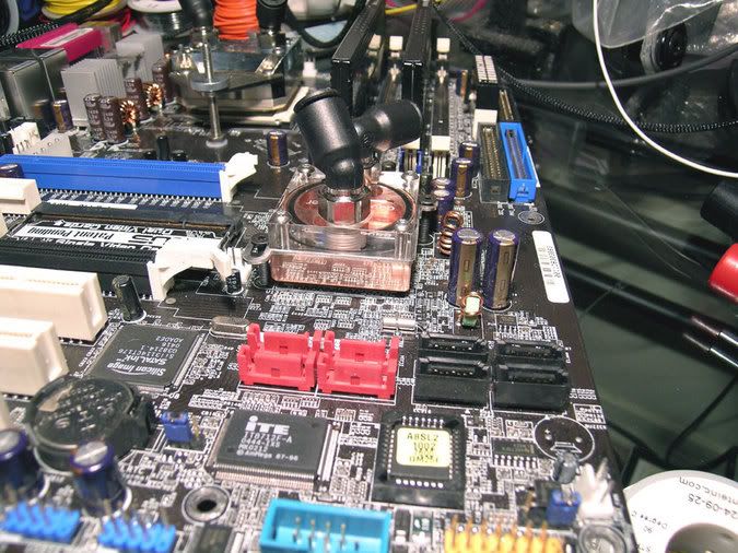
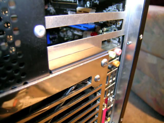
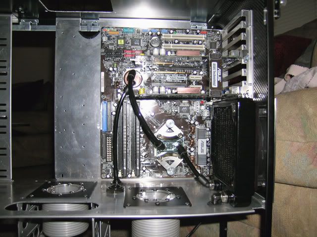
A couple of close ups of the NB and SLI action. If your really observant you might notice I didn't use those ugly looking MB hold down screws. Found another use for my buttonhead stainless screws. ;D
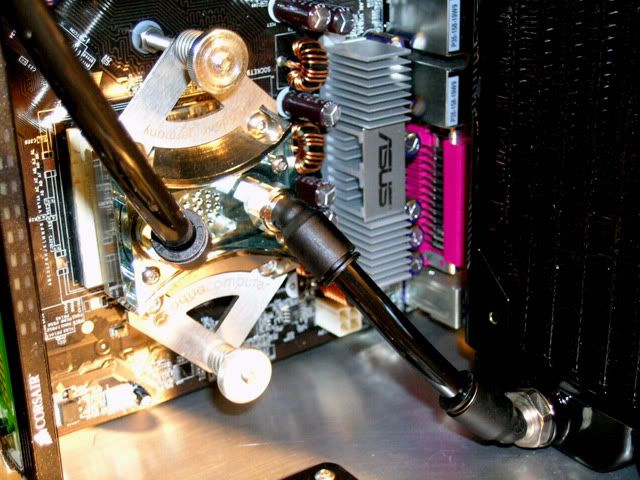
Here we are down near the bottom back of the case for a closeup of the radiator line going to the CPU cooler.
A close up of the NB return line where it goes through the bulkhead fitting. You can see the ATX connector on the left side that I painted a while back. This will be replaced with a black connector I got from A.C. Ryan. Dang those hairs! :
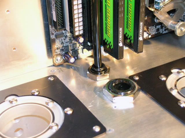
And of course a nice view of everything from the front of the case.
Here is the XT mounted loosely and shows the proper fastener sequence. If I ever take it off I think I will eliminate the plastic washer under the spring as it seems to hinder proper spring placement, but it also keeps the spring from digging into the mount and binding up so you pays your money and you take your chances. ;D
Here is the nut that goes on top of the spring and the studs that are included with the kit. I wanted to use the studs with my Asus A8N-SLI backing plate but they weren't long enough.
So I used the included machine screws. I assumed that the part with the upraised area on the nuts was to go on the spring side. Artic Silver 5 applied and springs are sitting on ready.
Here is the XT mounted and the nuts carefully tightened up. I used 1/4 turns alternating from side to side.
And last I have a side view for you. The instructions say that the springs should be compressed enough that a single sheet of paper can be slid between them.
That's it for now. Will try and get some more pics up later tonight with the MB permanently installed (I hope). :-/
Added:
All right I promised you guys some pics of the MB installed tonight so here it is. No tubing in yet and the video cards were put in just for show as they are missing the waterblocks.
All right I took pity on R1ckCa1n and decided that I could at least put some tubing in. The water flows from the pump > radiator > Cuplex XT > Twinplex > Aquatube. When my stuff shows up from Performance PCS tomorrow I can put the PSU in and start the wiring job.
Looking from the front of the case. The original plan was to run the return line from the NB right between the memory modules as it seemed like a straight shot and would probably be near invisible. Then I got to be thinking of adding some longer video cards down the line and decided that would be a problem.
So I decided to go outside the memory modules. Hopefully it will look okay...A couple of close ups of the NB and SLI action. If your really observant you might notice I didn't use those ugly looking MB hold down screws. Found another use for my buttonhead stainless screws. ;D
Here we are down near the bottom back of the case for a closeup of the radiator line going to the CPU cooler.
A close up of the NB return line where it goes through the bulkhead fitting. You can see the ATX connector on the left side that I painted a while back. This will be replaced with a black connector I got from A.C. Ryan. Dang those hairs! :
And of course a nice view of everything from the front of the case.
All right, now that the MB is in it is time to work on the PSU. Just to review a bit I am using a PCP&C Turbo Cool 510 SLI. Kind of noisy for someone who wants a silent PC, but I still got a few tricks up my sleeve. Here is the PSU area devoid of side panels and PSU.
And here is my PSU bolted to the back of my removable plate. You can see a silicon gasket I got from Vantec and dyed black along with the fan gaskets a while back. With the flash it looks kind of a sickly reddish blue, but in natural light it is black.
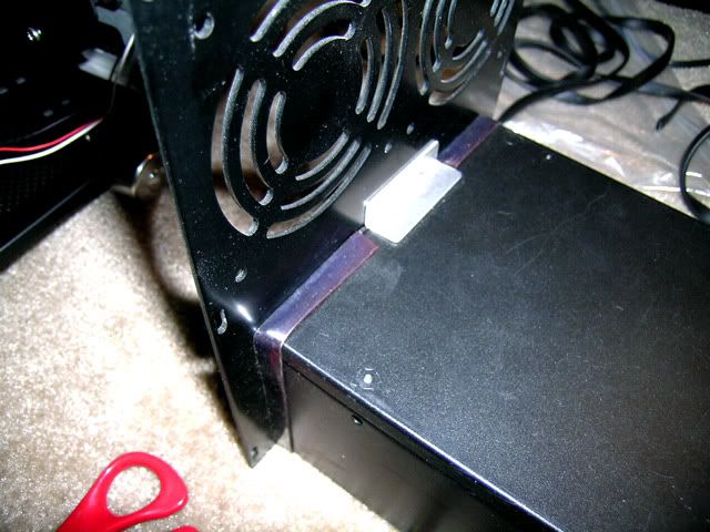
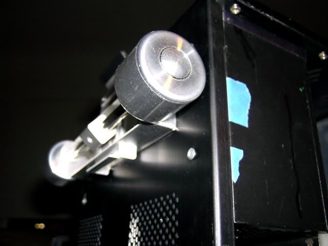
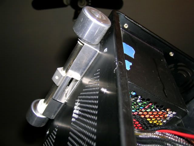
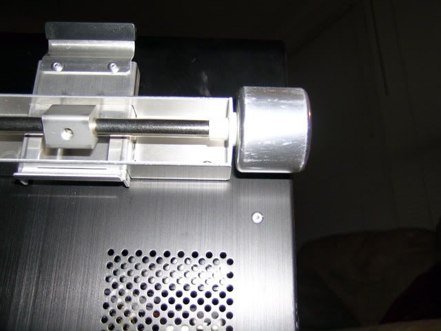
So the first thing is what some might consider some *bling* which it is, but it does serve a very important function. The PSU gasket isolates the back of the PSU from causing any vibration with the metal back plate and this rubber molding isolates the front of the PSU in the same manner. I got the molding from McMaster-Carr. If you want to know what that white stuff is I have no idea, but a little electronic spray cleaner should make it go bye-bye.
Here is a close up of the molding.
I just knew that I was going to have to take apart something. The radiator had to come out so I could see what I was doing with the 4 pin MB and SLI power looms.
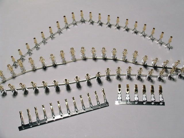
Got my shipment from Performance PCS today. I figure the gold plated pins don't really go with the motif, but who the heck is going to see them. Besides I have to shorten or lengthen most of the PSU looms so adding new connectors was easier than soldering wires to the shortened ones. Minor problem in that they didn't ship me what they said they were so I can't start the ATX loom until they ship me the balance. > However, I got plenty of round female molex pins so I can get to work on the HD, optical drives, and Aquaero wiring tomorrow.
Another fly in the ointment is that the PCP&C PSU has some holes in the case for adusting the three different voltage rails. One is located on the side for easy access, but the other two are located on the bottom of the PSU. The blue tape shows the area where these holes are located on the bottom. The problem here is that if I drill hole(s) for the access then it kind of looks like I will be drilling into the back wheel mount. This appears what I have to do as I was thinking about just lifting the PSU up and making adjustments, but when everything is in all the wiring will be secured directly to the case so the PSU would be a big hassle to move. I checked it with my dial calipers and it appears doable, but I won't know how it will work out till after I do it. So as I have said before you pays your money and you takes your chances. ;D
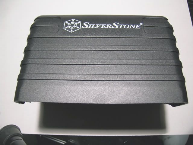
As I discussed a while back I spoke for about a half hour with a PCP&C engineer about using a fan that was quieter than the stock one. Unfortunately it is not possible to use another fan as it would severely compromise the efficiency and wattage output of the PSU. What they recommended was figuring out a way to deaden or redirect the reflected noise, from the fan, by using sound deadening materials behind my computer. The stuff they recommended to stick on my wall definitely didn't go with my house so that was out. However, when I was ordering from Performance PCS I noticed a really cool product made by Silverstone that looks like it may really fix this noise problem. It is called a Power Supply Acoustic Cover and it deadens noise and redirects the noise away from the wall. And since my PSU is next to the floor I think it will redirect all the sound into my carpet. I will let you know how this works when I get it turned on, but I suspect it will be a lot more quiet.
Well that is it for tonight and tomorrow I start sniping, soldering, and crimping my way to modding heaven.
And here is my PSU bolted to the back of my removable plate. You can see a silicon gasket I got from Vantec and dyed black along with the fan gaskets a while back. With the flash it looks kind of a sickly reddish blue, but in natural light it is black.
So the first thing is what some might consider some *bling* which it is, but it does serve a very important function. The PSU gasket isolates the back of the PSU from causing any vibration with the metal back plate and this rubber molding isolates the front of the PSU in the same manner. I got the molding from McMaster-Carr. If you want to know what that white stuff is I have no idea, but a little electronic spray cleaner should make it go bye-bye.
Here is a close up of the molding.
I just knew that I was going to have to take apart something. The radiator had to come out so I could see what I was doing with the 4 pin MB and SLI power looms.
Got my shipment from Performance PCS today. I figure the gold plated pins don't really go with the motif, but who the heck is going to see them. Besides I have to shorten or lengthen most of the PSU looms so adding new connectors was easier than soldering wires to the shortened ones. Minor problem in that they didn't ship me what they said they were so I can't start the ATX loom until they ship me the balance. >
However, I got plenty of round female molex pins so I can get to work on the HD, optical drives, and Aquaero wiring tomorrow.Another fly in the ointment is that the PCP&C PSU has some holes in the case for adusting the three different voltage rails. One is located on the side for easy access, but the other two are located on the bottom of the PSU. The blue tape shows the area where these holes are located on the bottom. The problem here is that if I drill hole(s) for the access then it kind of looks like I will be drilling into the back wheel mount. This appears what I have to do as I was thinking about just lifting the PSU up and making adjustments, but when everything is in all the wiring will be secured directly to the case so the PSU would be a big hassle to move. I checked it with my dial calipers and it appears doable, but I won't know how it will work out till after I do it. So as I have said before you pays your money and you takes your chances. ;D
As I discussed a while back I spoke for about a half hour with a PCP&C engineer about using a fan that was quieter than the stock one. Unfortunately it is not possible to use another fan as it would severely compromise the efficiency and wattage output of the PSU. What they recommended was figuring out a way to deaden or redirect the reflected noise, from the fan, by using sound deadening materials behind my computer. The stuff they recommended to stick on my wall definitely didn't go with my house so that was out. However, when I was ordering from Performance PCS I noticed a really cool product made by Silverstone that looks like it may really fix this noise problem. It is called a Power Supply Acoustic Cover and it deadens noise and redirects the noise away from the wall. And since my PSU is next to the floor I think it will redirect all the sound into my carpet. I will let you know how this works when I get it turned on, but I suspect it will be a lot more quiet.
Well that is it for tonight and tomorrow I start sniping, soldering, and crimping my way to modding heaven.
Well spent most of yesterday resizing pics at bit-tech's request. Also will be out of pocket for a few days. Some idiot hit my car while I was stopped and the guy must have been going at least 80 MPH (about 140 KPH) as witnesses said they were doing 50 and he went by them like they were standing still while he was swerving in and out of traffic. He lost control oh his vehicle and went into a four wheel slide and ended up hitting me while I was stopped at a stop sign on a cross street. This a%%hole even had the audacity to try and say it was my fault as I was loaded up into an ambulance. :
Well the long and short of it is that it might be a few days before I get feel like doing any modding. However, while I was in the ER yesterday I think I came up with a way to fix my PSU voltage adjustment problem. Time for more drill and dremel action.
Well the long and short of it is that it might be a few days before I get feel like doing any modding. However, while I was in the ER yesterday I think I came up with a way to fix my PSU voltage adjustment problem. Time for more drill and dremel action.
-