 25.04.2024, 09:13
 Sprache ändern
 Registrieren
 Anmelden
Sie sind nicht angemeldet.
Lieber Besucher, herzlich willkommen bei: Aqua Computer Forum. Falls dies Ihr erster Besuch auf dieser Seite ist, lesen Sie sich bitte die Hilfe durch. Dort wird Ihnen die Bedienung dieser Seite näher erläutert. Darüber hinaus sollten Sie sich registrieren, um alle Funktionen dieser Seite nutzen zu können. Benutzen Sie das Registrierungsformular, um sich zu registrieren oder informieren Sie sich ausführlich über den Registrierungsvorgang. Falls Sie sich bereits zu einem früheren Zeitpunkt registriert haben, können Sie sich hier anmelden.

- 1
- 2


Well the AQ5 xt has been working great for over a year and now suddenly issues.
Issue 1:
Some times at power on it fails to turn on Fan 1( master pump for me) and some times fails to provide rpm signal to the motherboard even when fan1 (pump) is running, and trapped air bubbles in Filter clearly showing water flow. Also in this failed state the case HDD led is lit.
Only solution so far is unplug the computer.
When it works...all works great.
Had odd sorts of issues with the aging p8z68 motherboard after a HDD failure, I updated AQ5 to latest firmware after cleaning installing - is their a known bug in the latest firmware???
Note: I have now replaced with P8Z77-m pro and the issues remain.
Issue 2:
The sweet looking filter arrived with a faulty open/close valve, after using it would always drip a few drops of coolant , a tough learning curve when the first lesson destroys a HD7970 graphics card
As it was not practical to post back to Europe I removed the handle from the faulty side and used it as a visual with the tri-led. Having replaced the motherboard board I changed the loop and trashed the terrible MIPS motherboard blocks (great build quality but hey CNC machines do the work, poor design, woefully restrictive and a thoughtless mounting system).
To attempt to get some function out of the filter I have now reversed input.. so the loop "snow" now collects on the top side of the mesh.
The problem is the loop flow is still way below expectations, do you have any data on the filters loop impact?
Have I compounded issues with reversing flow through filter?
And are replacement valves available?
I use the water block for the AQ5, is the block a major restriction?
Issue 3:
AS2013 is getting there, having saved profiles, including desktop layout I am disappointed to find that the desktop layout was not saved?
Dieser Beitrag wurde bereits 3 mal editiert, zuletzt von »Grasshopper« (5. Mai 2013, 03:11)
No idea on the Fan 1 output but I would try swapping something else and see if the problem follows the pump or stays on Fan 1 header.
Not sure what filter you are talking about, but filters can reduce flow. How much I have no practical experience with.
Yes AS2013-2 still has bugs.
No, the Aquaero water block is not very restrictive, there is no impingement plate like in a cpu block, it's pretty much straight through.
Not sure what filter you are talking about, but filters can reduce flow. How much I have no practical experience with.
Yes AS2013-2 still has bugs.
No, the Aquaero water block is not very restrictive, there is no impingement plate like in a cpu block, it's pretty much straight through.
The filter is:
http://shop.aquacomputer.de/product_info…roducts_id=2421 (0.32 PSI restriction)
Found out about the AQ5 water block from skinnylabs its 0.43 PSI @ 1G/M so its like half a cpu block of restriction.
any thoughts on loss of RPM signal to motherboard?
http://shop.aquacomputer.de/product_info…roducts_id=2421 (0.32 PSI restriction)
Found out about the AQ5 water block from skinnylabs its 0.43 PSI @ 1G/M so its like half a cpu block of restriction.
any thoughts on loss of RPM signal to motherboard?
Dieser Beitrag wurde bereits 2 mal editiert, zuletzt von »EnigmaG« (5. Mai 2013, 23:35)
For your rpm signal....you mean you have the tacho output from the Aquaero connected to your motherboard, right?
If it only works intermittently then maybe there is a problem with the cable itself. Check that the pins in the connectors make good contact or swap in another cable. Otherwise that only leaves a problem with the Aquaero itself.
As long as the Aquaero is powered up then it should have a signal on the tach header unless it's been disabled.
The only way to know if your filter is affecting flow in the loop is to measure the flow with / without the filter in place.
As far as the Aquaero water blocks, I have two Aquaero's with water blocks in my loop and they affect the flow very little.
My loop has components from a number of suppliers in Australia, as well direct import from Aquacomputers to finish the project.
The cpu and gpu blocks are Koolance, which are of the recent trend towards low restriction/high flow block design.http://skinneelabs.com/wp-content/uploads/370MasterTable.png
Computer had no problems for over a year, problem arose around the time of last firmware update, at that time computer had been unplugged for 2 weeks while I was inter state.
Problem of loss of tacho signal only occurs after cold start or wake up from long sleep.
Some times pump fails to start, AQ5 responds to the high flow sensor zero flow with alarm mode and switches the relay. And motherboard reports no tacho signal as correct
Other times pump, turns on AQ5 operates as normal, but the motherboard reports no tacho signal. And the ASUS z77m will not load OS with out cpu fan speed.
Not allowing the computer sleep, their is no problem with tacho signal, so I assume cable is not the issue.
Connecting the case fan to the motherboard cpu fan header, results in no issues with fan speed reporting.
Having duel pump( DDC 10W) redundant loop, with the 2 pumps on separate fan headers, swapping pumps plugs and shuffling profiles has not fixed the problem.
Just a thought...have you tried connecting the +5VSB from your psu to the Aquaero? That would keep the Aquaero powered up during sleep and maybe allow it to respond faster.
I use sleep, and I also use the relay to shut down the system on a low flow event. But I've always had the 5V standby connected on the Aquaero and I've had no problems.
I do not use the tacho output, however, as my Gigabyte board will not shut down on loss of cpu fan signal so I don't bother with it any more. When I did have it hooked up it seemed to work consistently though.
Otherwise I would make Aqua Computer aware of the issues in case it's something in the firmware they might need to change.
Thanks for replying sadly even setting bios to ignore fan rpm doesnt stop boot fail.Just a thought...have you tried connecting the +5VSB from your psu to the Aquaero? That would keep the Aquaero powered up during sleep and maybe allow it to respond faster.
I use sleep, and I also use the relay to shut down the system on a low flow event. But I've always had the 5V standby connected on the Aquaero and I've had no problems.
I do not use the tacho output, however, as my Gigabyte board will not shut down on loss of cpu fan signal so I don't bother with it any more. When I did have it hooked up it seemed to work consistently though.
Otherwise I would make Aqua Computer aware of the issues in case it's something in the firmware they might need to change.

I used the 53047 adaptor so AQ5 has standby power.
I am not sure how much communication the AQ5 has with the motherboard, I thought is was a totally independent microcomputer with a USB programming interface.

This is their forum and Shoggy has not responded....
That said checking back daily for a response, I am adding my opinion to other peoples issues so perhaps this is not a total loss.

Dieser Beitrag wurde bereits 2 mal editiert, zuletzt von »Grasshopper« (11. Mai 2013, 01:38)
Just installed a new D5 in my loop but it seems the RPM output is not working, tried all I can imagine.
First I connected the RPM with aquabus to a PA2 and forwarded the tachosignal to a display (Zlaman fan controller). Both the display and PA2 window in Aquasuite showed a fix RPM ~2700. I could adjust the power on PA2 and obvously this worked because the flow changed, but RPM didnt move.
After this tried connect the aquabus directly to a chassi fan header on MB, but in bios still 2700.
Today i tried with a new aquabus cable (the one provided with the pump), connected it to fan header on MB but now it seems there is no signal at all, bios shows N/A, tried two different fan headers.
Im using Aquasuite 2013. Settings looks ok.
The D5 is the one with USB, the D5 window in Aquasuite shows correct RPM ~5000.
Any advice?
It is quite some effort to take it out of the loop so want to do all I can before I return it.
I connected everyting before I switched on the power to test run the loop and noticed the low RPM.
After this I probably got abit frustrated trying alot of things trying to understand where the problem is and have now 2PA not working Seem not possible to reset.
The PA I have in loop with D5 and one PA I have in a separate loop with a DDC.
One is not starting at all and fails to load the USB driver.
One is giving power but not possible to manually adjust the power. Happened just after I disconnected the RPM cable while the power was on, after this it got stuck. Aquasuite shows 100% but considering the flow it is not on 100%.
Any advice would be appreciated alot
Have been using DDCs and PAs for couple of years and have been working fine, but now it seems bad luck hit me.
First I connected the RPM with aquabus to a PA2 and forwarded the tachosignal to a display (Zlaman fan controller). Both the display and PA2 window in Aquasuite showed a fix RPM ~2700. I could adjust the power on PA2 and obvously this worked because the flow changed, but RPM didnt move.
After this tried connect the aquabus directly to a chassi fan header on MB, but in bios still 2700.
Today i tried with a new aquabus cable (the one provided with the pump), connected it to fan header on MB but now it seems there is no signal at all, bios shows N/A, tried two different fan headers.
Im using Aquasuite 2013. Settings looks ok.
The D5 is the one with USB, the D5 window in Aquasuite shows correct RPM ~5000.
Any advice?
It is quite some effort to take it out of the loop so want to do all I can before I return it.
I connected everyting before I switched on the power to test run the loop and noticed the low RPM.
After this I probably got abit frustrated trying alot of things trying to understand where the problem is and have now 2PA not working
Seem not possible to reset.The PA I have in loop with D5 and one PA I have in a separate loop with a DDC.
One is not starting at all and fails to load the USB driver.
One is giving power but not possible to manually adjust the power. Happened just after I disconnected the RPM cable while the power was on, after this it got stuck. Aquasuite shows 100% but considering the flow it is not on 100%.
Any advice would be appreciated alot
Have been using DDCs and PAs for couple of years and have been working fine, but now it seems bad luck hit me.
Dieser Beitrag wurde bereits 1 mal editiert, zuletzt von »davidsson« (18. Mai 2013, 03:31)
Hi sorry for delay,
Perhaps I have misunderstood what you have experienced and tried so please correct me.
Thought I would start by comenting on your post and then list my expectations of the hardware.
Perhaps I have misunderstood what you have experienced and tried so please correct me.
Thought I would start by comenting on your post and then list my expectations of the hardware.
Just installed a new D5 in my loop but it seems the RPM output is not working, tried all I can imagine.
First I connected the RPM with aquabus to a PA2 and forwarded the tachosignal to a display (Zlaman fan controller). SO D5 power to PA2 and aquarbus D5 to PA2, then PA2 tacho to Zalman for display, where did you plug in the D5's tacho (RPM)Both the display and PA2 window in Aquasuite showed a fix RPM ~2700. I could adjust the power on PA2 and obvously this worked because the flow changed, but RPM didnt move.Appears D5 or PA2 is incorrectly reporting D5 speed. Does the second PA2 (ie PA2b) also report tacho of 2700rpm. (your thinking...but I already said it doesnt work...we will get that)
After this tried connect the aquabus directly to a chassi fan header on MB, but in bios still 2700.Aquabus is not like a tacho/rpm feedback, it allows daisy chaining devices so consider it to be more like a USB hub. You have 4 possible choices of connections to your motherboard, either/ or both the USB, 1 on D5 and 1 on a PA2. And thetacho/alarm cable from again either or both the D5 or the PA2. You can see the duplication, the USB D5 doesnt need a PA2

Today i tried with a new aquabus cable (the one provided with the pump), connected it to fan header on MB but now it seems there is no signal at all, bios shows N/A, tried two different fan headers. I would not expect any real value regardless of cable( as stated above)
Im using Aquasuite 2013. Settings looks ok. In configuration of the D5 did you choose aquabus or USB?
The D5 is the one with USB, the D5 window in Aquasuite shows correct RPM ~5000. Did you have D5 USB conected to motherboard USB for this?
Any advice?
It is quite some effort to take it out of the loop so want to do all I can before I return it. Hell yes
I connected everyting before I switched on the power to test run the loop and noticed the low RPM. do you have a flow meter
After this I probably got abit frustrated trying alot of things trying to understand where the problem is and have now 2PA not working, micro computers dont have rebuild options, if their program is corrupt, causing the problem, try to reinstall firmware, you may want to try doing this through Aquasuite 4.72.
The PA I have in loop with D5 and one PA I have in a separate loop with a DDC.
One is not starting at all and fails to load the USB driver. if you connect PA2b to PA2a via a aquabus cable and conect PA2a USB to motherboard can you communicate with PA2b
One is giving power but not possible to manually adjust the power. Happened just after I disconnected the RPM cable while the power was on, after this it got stuck. Aquasuite shows 100% but considering the flow it is not on 100%. flash firmware
Any advice would be appreciated alot
Have been using DDCs and PAs for couple of years and have been working fine, but now it seems bad luck hit me.
Aquacomputer gear is so wonderful, but it always appears it should come with a short course in "learn to speak German" , it sounds to me that what to plug in were has been the issue
I have 2 *10W DDc in series, as I am not about insane CPU overclocking, rather a silent option for cooling graphic card (as thermal solution is so limited by ATX motherboard design) One pump ramps up in 3 stages according to thermal load, the second joins in in the second two ramps. Radiator is 9 fan, (controlled in 2 sets, 3 + 6 ), runs passive unless gaming. DDC because thats what i had easy access to, and I use a AQ5 pro to control the 2 pumps and 2 fan clusters. I have case with a front door so I use the desktop to display water loop details.
Had I discovered the D5 USB perhaps I would have done things different.It appears to me the D5 gives 2 options
1 is that you power the pump via molex(HDD) and control it by USB to motherboard and using aquasuit, tacho signal to motherboard fan header or in your case Zaman. D5 temperature input frommeasureing temperature at output of Radiator. Set D5 control to be by USB. Us open hardware monitor to provide secondary temperature values for pump control.
2 is use aquabus connection to PA2 and also plug in PA2 USB to motherboard. perhaps Tacho/alarm of PA2 to Zalman. Use the second temperature sensor from PA2 to measure Radiator inlet. I would attempt to use AS23013 to control D5 via PA2 based on absolute difference between in/out temp, so that pump control is independent of room ambient temperature. Connect second PA2b to PA2a by aquabus connection. Remembering of cause that the PA2's need to have different ID's setup and control mode selected. That said perhaps the PA2.s being single channel controllers cannot function "bridged" and the 2 separate temperature sensors (in/out) cannot be used together in AS2013. Then I would attempt to use open hardware monitor to provide additional temperature values, as "target value" pump control not suitable in my climate.
It is possible you have a bad pump?
Thanks for help!
I think you understood quite correct yep I have a flowmeter, the older aquacomputer version without usb.
Some good news,
I managed to flash the firmware through 4.72 and now the PAa is working again.
And also got a reply from AQ on my mail about D5 RPM signal. Somewhat unexpected but now the 2700 makes sense and the D5 seems to be working fine
"the tach signal output is only an artificial signal to tell if the pump is running or not. It has nothing to do with the real speed of the pump.
An aquabus connection between the D5 and poweradjust 2 is not possible. These devices can only be connected to an aquaero 5. In this case you would also need a y-adapter to connect both of them. To have both devices available in the aquasuite you have to connect them via USB. Try it that way and everything should work. There is no real reset for the poweradjust controller. With the software you can load the factory defaults which is like a reset."
I dont have an AE5 yet but when I connect with USB both D5 and PA seems to be working as intended.
It would have been nice to be able to report the true RPM to my Zalman display but I can live with this "flaw"
I found out when D5 is configuered as "USB prio" then the RPM is switched off, which explains that I suddenly didnt see the 2700...
So now it is just the PAb, I have not tried yet, not really sure how to wire the dasiy chain, which headers? I guess connect the headers just next to the power inputs?
"absolute difference between in/out temp"
Here you mean delta temp between in/out on waterblock? Is it possible to do this in AS without an AE5?
I think you understood quite correct
yep I have a flowmeter, the older aquacomputer version without usb.Some good news,
I managed to flash the firmware through 4.72 and now the PAa is working again.
And also got a reply from AQ on my mail about D5 RPM signal. Somewhat unexpected but now the 2700 makes sense and the D5 seems to be working fine
"the tach signal output is only an artificial signal to tell if the pump is running or not. It has nothing to do with the real speed of the pump.
An aquabus connection between the D5 and poweradjust 2 is not possible. These devices can only be connected to an aquaero 5. In this case you would also need a y-adapter to connect both of them. To have both devices available in the aquasuite you have to connect them via USB. Try it that way and everything should work. There is no real reset for the poweradjust controller. With the software you can load the factory defaults which is like a reset."
I dont have an AE5 yet but when I connect with USB both D5 and PA seems to be working as intended.
It would have been nice to be able to report the true RPM to my Zalman display but I can live with this "flaw"
I found out when D5 is configuered as "USB prio" then the RPM is switched off, which explains that I suddenly didnt see the 2700...
So now it is just the PAb, I have not tried yet, not really sure how to wire the dasiy chain, which headers? I guess connect the headers just next to the power inputs?
"absolute difference between in/out temp"
Here you mean delta temp between in/out on waterblock? Is it possible to do this in AS without an AE5?
Good that you got a quick response from AQ and are for the most part, up and going.
I did find in a google search a good picture of AP2 layout, 2 3 pin sockets back to back in middle are, label 1 and 2 something.use aquabus cable to join the PA2a to PA2b by these. Aquabus socket on board is for connection to AQ5 aquabus.
get AQ5 pro or XT, dont get the LT, you have no alternative profile options.
Measuring difference between in.out of radiator is a way of setting up fan speeds independent for the most part
on room temperature, in my case computer room can vary between 12c -36c, so I cannot set fan/pump speed to fluid temperature/ room ambient temperature, other wise I would need multiple profiles , Summer, Winter etc. Dieser Beitrag wurde bereits 1 mal editiert, zuletzt von »Grasshopper« (23. Mai 2013, 07:21)
I've done a quick basic pic/guide for connecting the PA's e.t.c, Have a look HERE & see if it helps you out any. There are also other connection guides & how to set up guides I'm working on there so may be there's something there that can help to explain things about various Aquaero/Aqualis Items..So now it is just the PAb, I have not tried yet, not really sure how to wire the dasiy chain, which headers? I guess connect the headers just next to the power inputs?
"absolute difference between in/out temp"
Here you mean delta temp between in/out on waterblock? Is it possible to do this in AS without an AE5?
N.
Measuring difference between in.out of radiator is a way of setting up fan speeds independent for the most part [/align] on room temperature, in my case computer room can vary between 12c -36c, so I cannot set fan/pump speed to fluid temperature/ room ambient temperature, other wise I would need multiple profiles , Summer, Winter etc. [/align]
If you use the 'setpoint' controller option in Aquasuite using an ambient air/fluid temp delta as the datasource you wouldn't need to set profiles for different seasons. It is independent of seasonal variation in ambient temperature. It can take a bit of fiddling to get right for your individual machine but the results are worth the time experimenting with different setpoint settings. The fans and pumps only wind up when needed and the machine is whisper quiet for 99% of daily use.
I don't follow how measuring radiator in and out gives you a load based fan control?
When I set my fans to a set speed and start a GPU benchmark the water temps increase but the gap between rad water in and out stays at a fairly constant 0.4C ... meanwhile my Air/ water delta has jumped up to nearly 8C and my normal delta based fan control would have the fans wound up ages ago.
My delta controller does not change with the season. It just changes fan speeds from an idle delta of 4C up to a load delta of about 8C
Edit: Nevermind, I assume you must have been referring to radiator in / out air temps. Which is essentially the same thing as an air/water delta controller.
Dieser Beitrag wurde bereits 1 mal editiert, zuletzt von »Jakusonfire« (23. Mai 2013, 20:57)
delta cpu to fluid is ~5c, doubling flow will only reduce this by <1c, when gaming this rises to ~10c
cold (in) fluid to ambient (air) is ~5c no fans running (normal browsing usage), if I run all 9 fans I can reduce this down to 1.1c (~ 3c full load)
CPU temp = air + cold/air + CPU/fluid
ie cpu = 25 +5 + 5
as mentioned I have limited options to improve cpu/fluid and I am accepting of cold/air performance to have near silent computer.
Under normal use IN/OUT radiator delta is usually between 0.4c and 0.6c ( passive cooling), when gaming etc this will rise to about 1.2c, as around this value pump1 increased to 100%, pump2 is turned on to increase flow and 1 bank of 3 fans has turned on.
Computer is still very quiet.
To compensate for fluid/air temperature creep a second set of fans turns on when Fluid /AIR delta = 9c and turns off at 5c, now with 9 fans computer actually quite noisy.
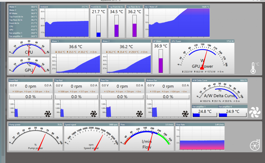
And of cause with the FLOW , IN and OUT this gives me estimate of heat being dissipated by the radiator, the "power measurement" ie 54W browsing, 220W playing BF3.
cold (in) fluid to ambient (air) is ~5c no fans running (normal browsing usage), if I run all 9 fans I can reduce this down to 1.1c (~ 3c full load)
CPU temp = air + cold/air + CPU/fluid
ie cpu = 25 +5 + 5
as mentioned I have limited options to improve cpu/fluid and I am accepting of cold/air performance to have near silent computer.
The area that has greatest choice is the radiator as I can adjust fluid flow and air flow, to measure the effect of my actions I measure the IN and OUT fluid temperature of the radiator. As an example at what point does increase air have a diminishing effect.
Under normal use IN/OUT radiator delta is usually between 0.4c and 0.6c ( passive cooling), when gaming etc this will rise to about 1.2c, as around this value pump1 increased to 100%, pump2 is turned on to increase flow and 1 bank of 3 fans has turned on.
Computer is still very quiet.
To compensate for fluid/air temperature creep a second set of fans turns on when Fluid /AIR delta = 9c and turns off at 5c, now with 9 fans computer actually quite noisy.
And of cause with the FLOW , IN and OUT this gives me estimate of heat being dissipated by the radiator, the "power measurement" ie 54W browsing, 220W playing BF3.
Dieser Beitrag wurde bereits 1 mal editiert, zuletzt von »Grasshopper« (25. Mai 2013, 13:16)
OK, but is still don't see what radiator water In / out delta has to do with a controller that is independent of ambient variation.
The In/Out Delta increases because you change the fan speeds, not as a result of load on the system. What triggers the extra pump to turn on, and the fans to start?
It sounds like the simple on off controller for the second set of fans is the one that is actually doing any water temp control. The Air/water delta controller.
The optimum Air /water deltas for a system does not change with the seasons.
OK, but is still don't see what radiator water In / out delta has to do with a controller that is independent of ambient variation.
The In/Out Delta increases because you change the fan speeds, not as a result of load on the system.
This is definitely not true in my system. When idling, my in/out delta is almost nothing....between 0.2 and 0.4 degrees Celsius. But when system is put under load, the in/out delta increases to as much as 4 degrees Celcius. This is all with a constant fan speed.
Using furmark to stress HD 7970 GPUOK, but is still don't see what radiator water In / out delta has to do with a controller that is independent of ambient variation.
The In/Out Delta increases because you change the fan speeds, not as a result of load on the system. What triggers the extra pump to turn on, and the fans to start?
It sounds like the simple on off controller for the second set of fans is the one that is actually doing any water temp control. The Air/water delta controller.
The optimum Air /water deltas for a system does not change with the seasons.
at start GPU 33c
almost instantly rises to 42c
after 4 minutes 43c
after 14 minutes 44c
water flow 180l/hr
radiator load 230 watts
3 fans running at 5.5v, ( in/out continue rise "curve control" of fans would have increased fan speed)
Interesting to note that fluid/air delta still ~5c and
difference from 42 to 44 is the rise in fluid in/out delta
So adding CPU to burn testing:
2600k CPU over clocked to 4.46G running prime95 (all cores 100%) + furmark HD7970 = ~ 350W radiator load
IN/OUT delta 1.6c stable ( but keep in mind now 9 fans running)
fluid/air stable 8.6c with second bank of 6 fans at not so noisy 7.8v,
As stated:
1)no fans are running during web surfing, typing,watching movies etc , so changes in in/out delta is not fans speed but heat load. Fans respond to heat load!
2)by 1.2c in/out delta things are turning on/increasing in speed to compete with increase heat load, this is achieved with curves based on in/out delta.
3)possible for computer to still have 1c in/out delta and have a fluid temperature of 60c, to to combat creeping fluid temperature the second set of fans (fan2) is bound to fluid/air delta.
4) fluid/air control means fan2 will cycle on and off, the two point control is set high so this happens as infrequently as possible.... keeping in mind this occurs more often in summer as AIR temp gets warmer, passive cooling capacity diminishes.
5) clearly my loop is geared to two modes, silent passive and acceptable noisy gaming.
Dieser Beitrag wurde bereits 2 mal editiert, zuletzt von »Grasshopper« (29. Mai 2013, 13:43)
Ok, so all fans off and a GPU benchmark for 5 minutes.As you can see the air/water delta immediately shoots up along with water temps.
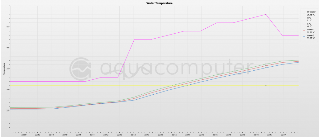
Purple is GPU temps, three water sensors are the lines climbing together including green rad in and red rad out. As you can see when the benchmark starts the water temps climb together. A 10C increase and the rad in/out remains constant.
As you said yourself water temps can be 60C and rad in out delta can still be low. The Air/water delta controller is what is stopping temps getting out of control so how is a rad in out controller independent of ambient temps. Its independent of it in the sense that it pays no attention to it at all and a second controller is needed.
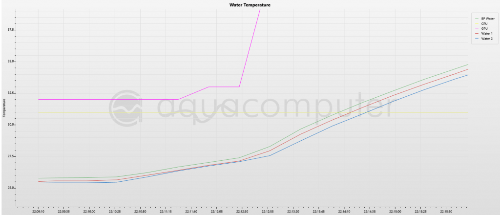
Close up of the water temp chart,
Rad in ... Green
Rad out .. Red
Dieser Beitrag wurde bereits 3 mal editiert, zuletzt von »Jakusonfire« (29. Mai 2013, 15:11)
- 1
- 2
Ähnliche Themen
-
 English forum »
-
 MPS 400 reporting 3.86 gal/hour?
(11. März 2013, 15:57)
MPS 400 reporting 3.86 gal/hour?
(11. März 2013, 15:57)
-
- English forum »
-
Updated aquasuite/firmware stabillity issues??
(19. November 2012, 20:16)
-
- English forum »
-
fan 3 not showing rpm yet still running
(23. Juni 2012, 04:23)
-
- English forum »
-
Problem with Fan RPM reporting
(24. Dezember 2011, 23:29)
-