 17.04.2024, 01:42
 Sprache ändern
 Registrieren
 Anmelden
Sie sind nicht angemeldet.

Hey all,
I have been using my Aquaero 6 XT for about 3 months and I'm absolutely loving it thus far. I hesitated at the premium price tag for years, but now wish I had bought it ages ago. Totally worth every penny.
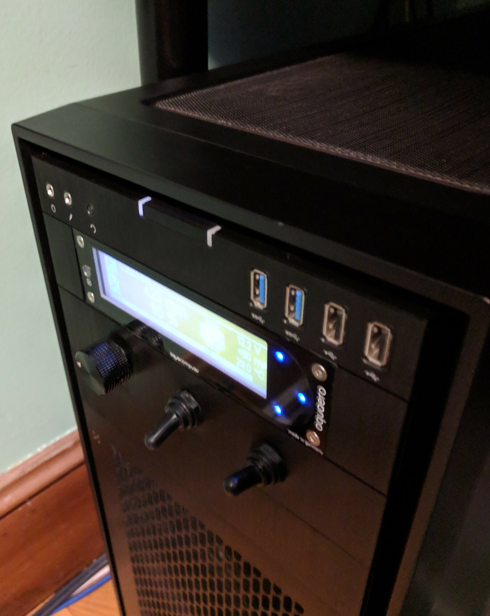
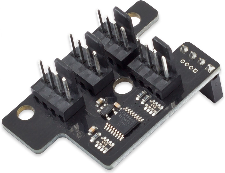
Anyway, when I first installed the Aquaero I just installed it with some crappy old two pin Phobya inline water temp sensors I bought several years ago before I knew better. They work, but they are not the most accurate. Essentially their design is just one of those flat flexible air temp sensors wrapped around a metal male to female G1/4 extender, and not wrapped very well.So, I decided to upgrade my temperature sensors, and got 4x Aquacomputer Calitetemp Aquabus sensors and a 4x aquabus board. I haven't received them yet, but I have a question so I know what to do when they get here.The Aquabus 4x adapter does not have labeled inputs like the two pin temperature sensor inputs on the Aquaero do:
How do I know which sensor is which in the Aquasuite software when I am setting up my pump and fan speed controls?
Do I just have to plug them in one by one, name them appropriately (like GPU temp in, GPU temp out, CPU temp In, CPU Temp out) power down, and install the next one, etc. etc?
Or do they have some sort of unique identifiers?
Once installed, is there any risk of them moving around or should they stay the same indefinitely?
Much obliged,
Matt
I have been using my Aquaero 6 XT for about 3 months and I'm absolutely loving it thus far. I hesitated at the premium price tag for years, but now wish I had bought it ages ago. Totally worth every penny.
Anyway, when I first installed the Aquaero I just installed it with some crappy old two pin Phobya inline water temp sensors I bought several years ago before I knew better. They work, but they are not the most accurate. Essentially their design is just one of those flat flexible air temp sensors wrapped around a metal male to female G1/4 extender, and not wrapped very well.So, I decided to upgrade my temperature sensors, and got 4x Aquacomputer Calitetemp Aquabus sensors and a 4x aquabus board. I haven't received them yet, but I have a question so I know what to do when they get here.The Aquabus 4x adapter does not have labeled inputs like the two pin temperature sensor inputs on the Aquaero do:
How do I know which sensor is which in the Aquasuite software when I am setting up my pump and fan speed controls?
Do I just have to plug them in one by one, name them appropriately (like GPU temp in, GPU temp out, CPU temp In, CPU Temp out) power down, and install the next one, etc. etc?
Or do they have some sort of unique identifiers?
Once installed, is there any risk of them moving around or should they stay the same indefinitely?
Much obliged,
Matt
Dieser Beitrag wurde bereits 4 mal editiert, zuletzt von »mattlach« (23. März 2019, 23:43)
I asked that question when the device was introduced, but there was never an answer or reply.
I just received my aquabus X4 and 2 calitemps and had started to play around with them when my primary machine died.
Best I remember, the top/outside port is one, the middle port is two, the bottom port is three and the port by itself is four.
Hopefully you can confirm this by applying heat (touching them?) and seeing which sensor in the aquasuite moves.
IMPORTANT!!!
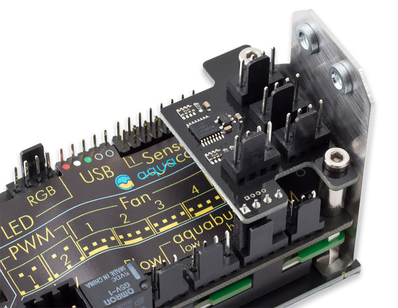
Do NOT assemble the entire thing and expect to be able to plug the calitemps into the aquabus X4.
Two of the ports conflict with the aquaero mounting bracket screw rivets, one you may be able to force, but the other you will not plug in.
You need to loosen the two front screws on the aquaero so the mounting bracket can be tilted out allowing the plugs to be plugged in.
Then you can tighten the front screws securing the mounting bracket back in.
I believe there is sufficient room (barely) once the plugs are installed.
The first picture below shows the aquabus X4 installed on the product page, but the mounting screw rivets are truncated.
In the second picture you can see the actual length of the aquaero mounting screw rivets.

I just received my aquabus X4 and 2 calitemps and had started to play around with them when my primary machine died.
Best I remember, the top/outside port is one, the middle port is two, the bottom port is three and the port by itself is four.
Hopefully you can confirm this by applying heat (touching them?) and seeing which sensor in the aquasuite moves.
IMPORTANT!!!
Do NOT assemble the entire thing and expect to be able to plug the calitemps into the aquabus X4.
Two of the ports conflict with the aquaero mounting bracket screw rivets, one you may be able to force, but the other you will not plug in.
You need to loosen the two front screws on the aquaero so the mounting bracket can be tilted out allowing the plugs to be plugged in.
Then you can tighten the front screws securing the mounting bracket back in.
I believe there is sufficient room (barely) once the plugs are installed.
The first picture below shows the aquabus X4 installed on the product page, but the mounting screw rivets are truncated.
In the second picture you can see the actual length of the aquaero mounting screw rivets.
Dieser Beitrag wurde bereits 1 mal editiert, zuletzt von »InfoSeeker« (24. März 2019, 04:42)
I asked that question when the device was introduced, but there was never an answer or reply.
I just received my aquabus X4 and 2 calitemps and had started to play around with them when my primary machine died.
Best I remember, the top/outside port is one, the middle port is two, the bottom port is three and the port by itself is four.
Hopefully you can confirm this by applying heat (touching them?) and seeing which sensor in the aquasuite moves.
IMPORTANT!!!
Do NOT assemble the entire thing and expect to be able to plug the calitemps into the aquabus X4.
Two of the ports conflict with the aquaero mounting bracket screw rivets, one you may be able to force, but the other you will not plug in.
You need to loosen the two front screws on the aquaero so the mounting bracket can be tilted out allowing the plugs to be plugged in.
Then you can tighten the front screws securing the mounting bracket back in.
I believe there is sufficient room (barely) once the plugs are installed.
The first picture below shows the aquabus X4 installed on the product page, but the mounting screw rivets are truncated.
In the second picture you can see the actual length of the aquaero mounting screw rivets.
Thank you for your reply.
Geez. That seems like kind of a design flaw.
I wonder if you have to mount it directly to the Aquaero like that, or if you can use some sort of aquabus extension cable from the port on the Aquaero to the x4 adapter, and place the adapter in a more convenient location, maybe mounted with some double sided tape...
You know, something like this.
Seems to be a standard 4-pin fan cable though, so there are likely many local alternatives that would work.
With the way my top radiator is mounted, the 5.25" bays are kind of a tight fit, so it is really difficult to plug things into the back of the Aquaero as it is. I understand multiple Calitetemp sensors can be finicky (since they can't use standard splitters) so I wonder if using an extension cable before the X4 board would be fine, or if it would cause electrical issues...
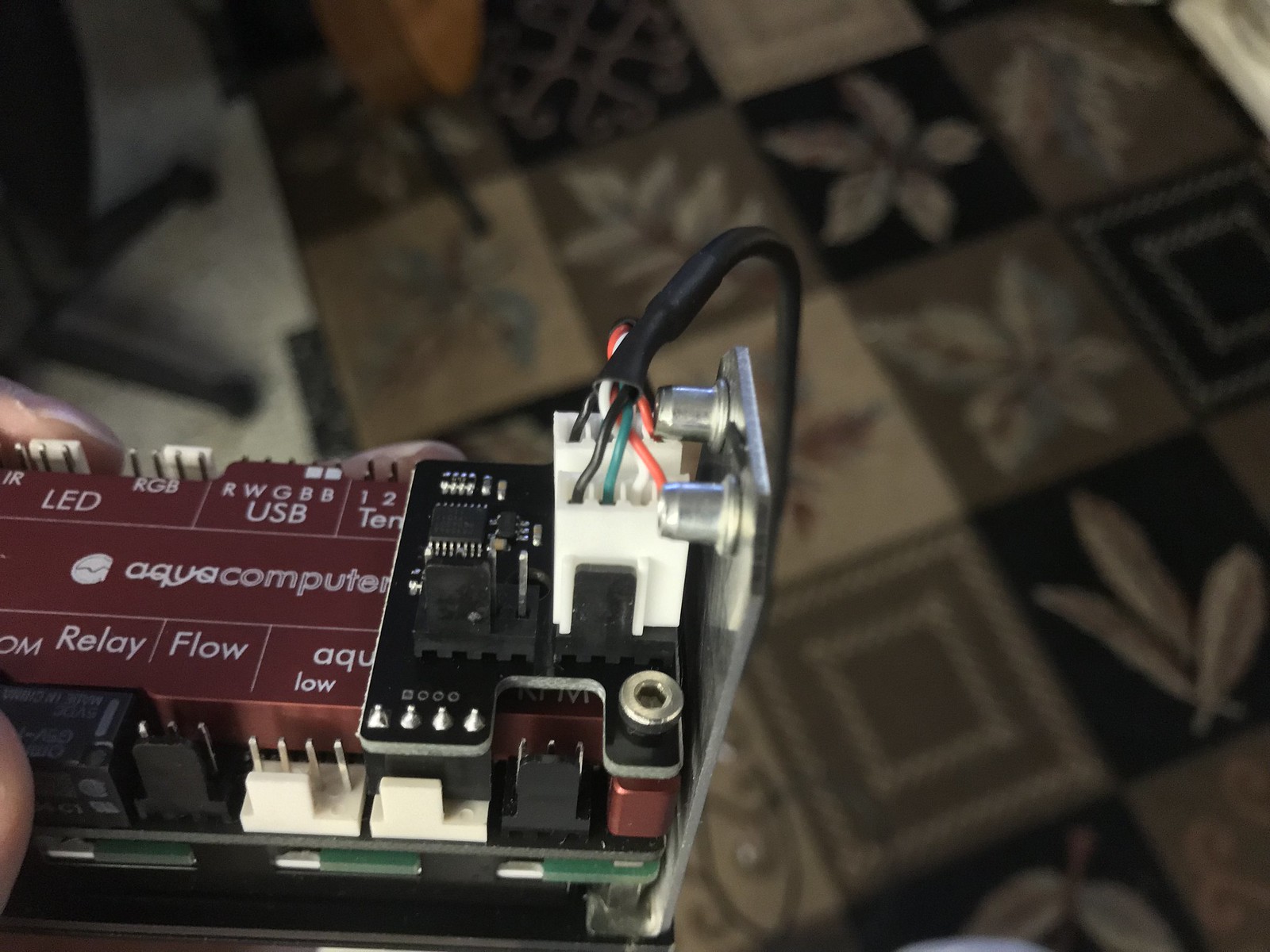
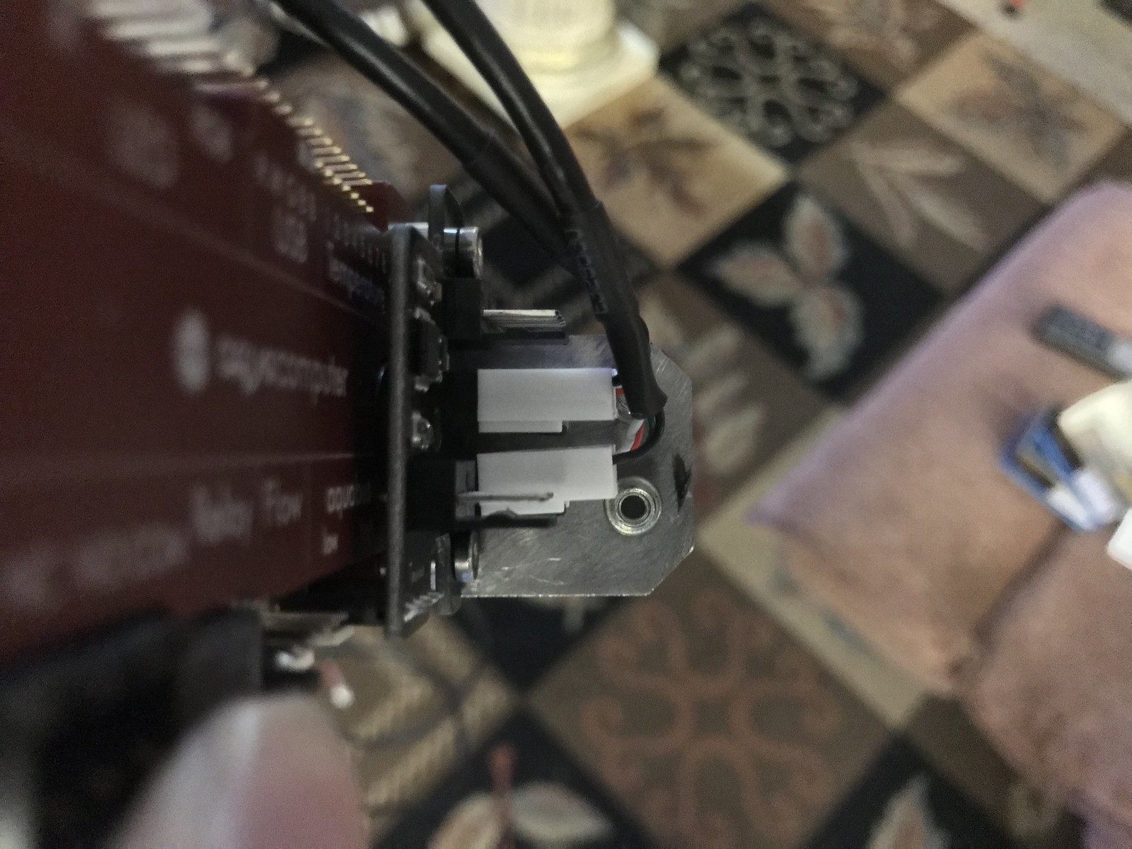
I had issues installing the X4 to the AQ6. Couldn't believe what I was witnessing and how could this design flaw have been missed. Regardless I still made it work.
Here are some images to paint the picture on what went on.

I thought it was going to cut the wire while pressing down on the female header.

Here are some images to paint the picture on what went on.
I thought it was going to cut the wire while pressing down on the female header.
Dieser Beitrag wurde bereits 1 mal editiert, zuletzt von »GTXJackBauer« (31. März 2019, 03:32)
At the design stage this would not have been a difficult fix.
Simply move the two ports in conflict with the screw rivets to the left above the current single port, and move the electronics under the screw rivets.
aquacomputer is generally meticulous with their designs... whomever was in charge of this project failed.
In my mind it is worth a remake and recall.
At the design stage this would not have been a difficult fix.
Simply move the two ports in conflict with the screw rivets to the left above the current single port, and move the electronics under the screw rivets.
aquacomputer is generally meticulous with their designs... whomever was in charge of this project failed.
In my mind it is worth a remake and recall.
Exactly what I was thinking with all that room there. I think it could have been planned as such but somehow it slipped through the cracks. Maybe a late night mistake.
I had issues installing the X4 to the AQ6. Couldn't believe what I was witnessing and how could this design flaw have been missed. Regardless I still made it work.
Yeah, I think I am just going to use a short 4 pin fan extension cable, and then double sided tape the x4 board somewhere nearby in the case. That should make this a little easier to deal with.
Here are some images to paint the picture on what went on.
I thought it was going to cut the wire while pressing down on the female header.
Yours looks very different than mine.
What is that red thing all along the back?
Dieser Beitrag wurde bereits 1 mal editiert, zuletzt von »mattlach« (16. April 2019, 02:49)
What is that red thing all along the back?
That is the optional heatsink. Helps dissipate any heat generated from the controller.
I had issues installing the X4 to the AQ6. Couldn't believe what I was witnessing and how could this design flaw have been missed. Regardless I still made it work.
Yeah, so I did as planned, used a spare Noctua 4-pin fan extension cable I had laying around to place the X4 board remotely. I used 3M double sided mounting tape, to tape it in a spot on the back of the motherboard tray, where there was a hole poking through so I could connect the connector on the back. You just have to watch out and make sure you get the pin orientation right, as the X4 board does not have any keying, as it relies on its install orientation on the Aquaero for orientation.
In my testing, the connector on its own wound up being Calitetemp 1, then the top connector on the right was 2, middle was 3 and bottom was 4.
I used a USB plug to internal header adapter cable in order to plug in to my laptop, so I could run Aquasuite and identify the temperature sensors while my loop was apart, and the system wasn't running.
Dieser Beitrag wurde bereits 1 mal editiert, zuletzt von »mattlach« (22. April 2019, 20:27)
What is that red thing all along the back?
That is the optional heatsink. Helps dissipate any heat generated from the controller.
Interesting.
When would one need this? Is this only for people who use a large number of voltage controlled fans? I'd imagine the resistors would create a good amount of heat if that is the case.
Personally I use three standard temp sensors, 4x Calitetemp sensors, a flow sensor, two PWM outputs for fans and one PWM output for my pump.
The PWM outputs don't even draw power from the Aquaero. I use them just for control.
I'd imagine in this setup, heat is less of an issue?
I am considering adding PID style Setpoint control to my system though. I wonder if this results in added processing and thus more heat.
I would probably recommend this if you're almost at 30w per channel for example but most of us I don't think aren't even close but I still like using it to help dissipate any heat since that area doesn't have too much air flow to begin with but for piece of mind.
Ah, cool. I'm guessing that since I am pulling 0W from any channel, this is something I probably don't have to worry about :p
THe place where mine is installed is a real pain to get to, so I'd rather not take it out to install a heatsink at this point.
I'm dealing with this now. I also have the heatsink, where did you get the spacers to use with it?
I had issues installing the X4 to the AQ6. Couldn't believe what I was witnessing and how could this design flaw have been missed. Regardless I still made it work.
Here are some images to paint the picture on what went on.
I thought it was going to cut the wire while pressing down on the female header.
Ähnliche Themen
-
 English forum »
-
 Aquabus D5 pump not being detected by aquaero 6
(15. Januar 2018, 20:03)
Aquabus D5 pump not being detected by aquaero 6
(15. Januar 2018, 20:03)
-
- English forum »
-
Connecting it all
(10. Juli 2016, 14:17)
-
- English forum »
-
Proper connection Aquaero 6 PRO + D5
(7. Mai 2015, 19:08)
-
- English forum »
-
Aqualis XT fill sensor Aquabus vs USB
(11. Dezember 2014, 21:14)
-
- English forum »
-
Aquaero Aquastream Connection Quaestion
(14. März 2008, 19:46)
-