 24.04.2024, 22:24
 Sprache ändern
 Registrieren
 Anmelden
Sie sind nicht angemeldet.
Lieber Besucher, herzlich willkommen bei: Aqua Computer Forum. Falls dies Ihr erster Besuch auf dieser Seite ist, lesen Sie sich bitte die Hilfe durch. Dort wird Ihnen die Bedienung dieser Seite näher erläutert. Darüber hinaus sollten Sie sich registrieren, um alle Funktionen dieser Seite nutzen zu können. Benutzen Sie das Registrierungsformular, um sich zu registrieren oder informieren Sie sich ausführlich über den Registrierungsvorgang. Falls Sie sich bereits zu einem früheren Zeitpunkt registriert haben, können Sie sich hier anmelden.

I have need of an 'Until' function in the Virtual Software Sensors, and I have not been able to define it yet.
What I want to do is trigger on A and then remain triggered Until B de-triggers
e.g. when A goes to 1, X goes to & remains at 1, until B drops to 0
The purpose being to trigger high fan action on hot temp, then not stop when below hot temp, but go all the way to low temp.
Any thoughts?
What I want to do is trigger on A and then remain triggered Until B de-triggers
e.g. when A goes to 1, X goes to & remains at 1, until B drops to 0
The purpose being to trigger high fan action on hot temp, then not stop when below hot temp, but go all the way to low temp.
Any thoughts?
Dieser Beitrag wurde bereits 1 mal editiert, zuletzt von »InfoSeeker« (6. März 2022, 20:49)
Isn't that a classic flip flop logic? You can simulate that with two not and or elements:

https://en.wikipedia.org/wiki/Flip-flop_…29#SR_NOR_latch
https://en.wikipedia.org/wiki/Flip-flop_…29#SR_NOR_latch
Dieser Beitrag wurde bereits 1 mal editiert, zuletzt von »Grestorn« (6. März 2022, 22:20)
Intel 12900K - Asus Maximus z690 Formula - 2x16 GB G.Skill DDR5 6000/36 - NVidia RTX 4090 FE
Acer Predator x27 - Thermaltake Core P5 - Corsair HX850i
-> Bilder und weitere Details <-
Acer Predator x27 - Thermaltake Core P5 - Corsair HX850i
-> Bilder und weitere Details <-
I have need of an 'Until' function in the Virtual Software Sensors, and I have not been able to define it yet.
What I want to do is trigger on A and then remain triggered Until B de-triggers
e.g. when A goes to 1, X goes to & remains at 1, until B drops to 0
The purpose being to trigger high fan action on hot temp, then not stop when below hot temp, but go all the way to low temp.
Any thoughts?
The simple way of approaching that (although it is a little cruder) is to add An Off Delay from the Functions so that once the triigger has gone from 1 to 0 it remains latched on for x seconds.
You can see how I use it at the following link
PID controller tuning
I am trying to follow the logic in this diagram. The AND gate will output 0 until CPU Temp is >= 80°C. When CPU Temp hits 80°C, the AND gate output will go to1, the switch will go to input B and the output will go to 100 (max). OK so far. Now as CPU temp drops, as soon as it goes under 80°C the top conditional will go to 0 so the AND gate output will go to 0 and the switch will switch back to input A. I don't see how the output will stay at 100 until the CPU Temp drops to 50°C. What am I missing here?Although this I think more accurately represents what you are looking to achieve
[attach]9258[/attach]
I had an off delay, but as I do not know how long I would be in a heavy load conditions, thus it would cycle over time.
I am going to try to implement this flip-flop thingy as soon as I figure out how to implement it.
I can't seem to be able to do it, because the Aquasuit doesn't allow for recursive logic...
Intel 12900K - Asus Maximus z690 Formula - 2x16 GB G.Skill DDR5 6000/36 - NVidia RTX 4090 FE
Acer Predator x27 - Thermaltake Core P5 - Corsair HX850i
-> Bilder und weitere Details <-
Acer Predator x27 - Thermaltake Core P5 - Corsair HX850i
-> Bilder und weitere Details <-
I am trying to follow the logic in this diagram. The AND gate will output 0 until CPU Temp is >= 80°C. When CPU Temp hits 80°C, the AND gate output will go to1, the switch will go to input B and the output will go to 100 (max). OK so far. Now as CPU temp drops, as soon as it goes under 80°C the top conditional will go to 0 so the AND gate output will go to 0 and the switch will switch back to input A. I don't see how the output will stay at 100 until the CPU Temp drops to 50°C. What am I missing here?Although this I think more accurately represents what you are looking to achieve
[attach]9258[/attach]
Ok so as the temperature (A) passes the LOW figure(B) that outputs 1 as it is >=A
att his point the AND gate wont fire as only its Bis 1
As the Temp (now as B) passes the High (A) the <= outputs 1 as A is now Less than B
At this stage the AND gate outputs a 1 which switches the final switch from A to B and therefore sets the Out figure to the "Set to Max" Figure
As the temp
oh bugger that doesn't work does it lol
/me wanders off..................................
I had an off delay, but as I do not know how long I would be in a heavy load conditions, thus it would cycle over time.
I am going to try to implement this flip-flop thingy as soon as I figure out how to implement it.
I can't seem to be able to do it, because the Aquasuit doesn't allow for recursive logic...
Have you taken a loook at my method that uses load & time linked to fan curves rather than siwtching on temp?
PID controller tuning
OK so I am not crazy. I think it can be fixed by adding and OR gate between the AND gate output and the switch input. The OR gate would be controlled by a conditional on the low temp value. I was going to dig into it but now I am thinking that the Flip Flop logic construct suggested by Grestorn may work with less logic. I am just not sure that a NOR Latch is the best one. There are a bunch of variations of the Flip Flop logic construct. NOR Latch, NAND Latch, JK Latch etc. I think one of these may be the most direct way to implement this.I am trying to follow the logic in this diagram. The AND gate will output 0 until CPU Temp is >= 80°C. When CPU Temp hits 80°C, the AND gate output will go to1, the switch will go to input B and the output will go to 100 (max). OK so far. Now as CPU temp drops, as soon as it goes under 80°C the top conditional will go to 0 so the AND gate output will go to 0 and the switch will switch back to input A. I don't see how the output will stay at 100 until the CPU Temp drops to 50°C. What am I missing here?
Ok so as the temperature (A) passes the LOW figure(B) that outputs 1 as it is >=A
att his point the AND gate wont fire as only its Bis 1
As the Temp (now as B) passes the High (A) the <= outputs 1 as A is now Less than B
At this stage the AND gate outputs a 1 which switches the final switch from A to B and therefore sets the Out figure to the "Set to Max" Figure
As the temp
oh bugger that doesn't work does it lol
/me wanders off..................................
Update- I tested this FIXED and it seems to work. Going to play with the Flip Flop option later (supposed to be working now...) I had to increase the Low Temp constant because my 5950X is running over 50°C because its really hot in the room I am in.
Update 2 - I have confirmed what Grestron said a few posts back - AQS does not seem to allow recursive logic. I can make 2 OR gates "OR-A" and OR-B" I can connect the output of OR-A to an input of OR-B but then I cannot connect the output of OR-B to an input of OR-A. So I can't make the flip flop. WAH!
Dieser Beitrag wurde bereits 2 mal editiert, zuletzt von »Speedy-VI« (7. März 2022, 23:09)
Have you taken a loook at my method that uses load & time linked to fan curves rather than siwtching on temp?
PID controller tuning
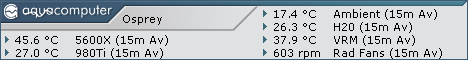
Yes, am currently triggering all fans when the PSU puts out more than 350 Watts. (psu.jpg)
Still would like to take it to temp sense, not giving up yet.
Goddammit that pissed me off...
that flip flop was annoying to make :p
I think i got it. it's a bit convoluted but i've watched it work for the last 5 minutes :p

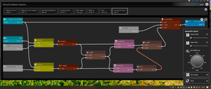
There's the upper and lower trigger temperature setpoints, to start and stop the fan boost.
The way it works is overriding the temperature used to control the fan speed.
If the temperature goes beyond the upper setpoint, the real sensor value is overriden by a value of your choice.
This fake temp is kept active until the real sensor temp drops below the lower boost setpoint. then normal control is restored, until the temperature goes again over the upper setpoint.
The flipflop is made through upper and lower trigger feeding an OR gate, and the output of that gate refreshes the output of two memory outputs.
Since the lower temp rigger is inverted, and with the help of the output AND gate, we get a logic output changing to 1 when the water is too hot, and to 0 when it has been cooled :p
the picture explains it better than me lol! Have a crack at it, put the sensors you use, tweak the fixed values, see how it goes
that flip flop was annoying to make :p
I think i got it. it's a bit convoluted but i've watched it work for the last 5 minutes :p
There's the upper and lower trigger temperature setpoints, to start and stop the fan boost.
The way it works is overriding the temperature used to control the fan speed.
If the temperature goes beyond the upper setpoint, the real sensor value is overriden by a value of your choice.
This fake temp is kept active until the real sensor temp drops below the lower boost setpoint. then normal control is restored, until the temperature goes again over the upper setpoint.
The flipflop is made through upper and lower trigger feeding an OR gate, and the output of that gate refreshes the output of two memory outputs.
Since the lower temp rigger is inverted, and with the help of the output AND gate, we get a logic output changing to 1 when the water is too hot, and to 0 when it has been cooled :p
the picture explains it better than me lol! Have a crack at it, put the sensors you use, tweak the fixed values, see how it goes
WOW!!Goddammit that pissed me off...
that flip flop was annoying to make :p
I think i got it. it's a bit convoluted but i've watched it work for the last 5 minutes :p
There's the upper and lower trigger temperature setpoints, to start and stop the fan boost.
The way it works is overriding the temperature used to control the fan speed.
If the temperature goes beyond the upper setpoint, the real sensor value is overriden by a value of your choice.
This fake temp is kept active until the real sensor temp drops below the lower boost setpoint. then normal control is restored, until the temperature goes again over the upper setpoint.
The flipflop is made through upper and lower trigger feeding an OR gate, and the output of that gate refreshes the output of two memory outputs.
Since the lower temp rigger is inverted, and with the help of the output AND gate, we get a logic output changing to 1 when the water is too hot, and to 0 when it has been cooled :p
the picture explains it better than me lol! Have a crack at it, put the sensors you use, tweak the fixed values, see how it goes
I need to stare at this for awhile. Yesterday I determined that you can't just make a classic flip flip out of a few OR gates and NOT gates because AQS does not allow the recursive connections. I am going to replicate this in my playground and then play around with it. You have a couple of things in there that I have never used before, so uncharted territory for me. This is what I love about AQS - if there is a will, there is a way (probably). Kudos for figuring this out.
Goddammit that pissed me off...
that flip flop was annoying to make :p
I think i got it. it's a bit convoluted but i've watched it work for the last 5 minutes :p
There's the upper and lower trigger temperature setpoints, to start and stop the fan boost.
The way it works is overriding the temperature used to control the fan speed.
If the temperature goes beyond the upper setpoint, the real sensor value is overriden by a value of your choice.
This fake temp is kept active until the real sensor temp drops below the lower boost setpoint. then normal control is restored, until the temperature goes again over the upper setpoint.
The flipflop is made through upper and lower trigger feeding an OR gate, and the output of that gate refreshes the output of two memory outputs.
Since the lower temp rigger is inverted, and with the help of the output AND gate, we get a logic output changing to 1 when the water is too hot, and to 0 when it has been cooled :p
the picture explains it better than me lol! Have a crack at it, put the sensors you use, tweak the fixed values, see how it goes
Nice, seems to work from the quick test I've just run.
Now to see if I can work all that into my routine to replace the time delay off, that's a job for tomorrow
So rather than try & build @Speedy-VI 's work into my existing Load & Time Fan Control (which would have looked messy) I've taken the simpler approach.
Use the Load & Temperature control Virtual Sensors as inputs on a third Virtual sensor which sends the Max value from either of the first two to the fan controls.
Fan_Control_Load.jpg
Fan_Control_Temperature.jpg
Fan_Control.jpg
Use the Load & Temperature control Virtual Sensors as inputs on a third Virtual sensor which sends the Max value from either of the first two to the fan controls.
Fan_Control_Load.jpg
Fan_Control_Temperature.jpg
Fan_Control.jpg
Dieser Beitrag wurde bereits 1 mal editiert, zuletzt von »WinstonWoof« (9. März 2022, 08:42)
I tweaked it slightly to replace the upper trigger by an aquasuite input, since i have no need for the emergency function. the input injects the value 20 in the upper trigger. The reset button just resets that input to 0
When i finish gaming at night, i just click boost and reset, and the PC will cool off quickly until the water is 4° over ambient. I used to do that manually with the fan offsets, but i may remove all that part of the inputs window actually
It was useful after all hehe
When i finish gaming at night, i just click boost and reset, and the PC will cool off quickly until the water is 4° over ambient. I used to do that manually with the fan offsets, but i may remove all that part of the inputs window actually
It was useful after all hehe
Dieser Beitrag wurde bereits 1 mal editiert, zuletzt von »Remayz« (9. März 2022, 12:28)
Interesting solutions.
I would not be averse to the authors posting an exported virtual sensor.
I know the sources would require updating, but it would help sight challenged folks like me. :)
Note to aquasuite developers.
The "X=mem(A) function appears to have a bug.
I would not be averse to the authors posting an exported virtual sensor.
I know the sources would require updating, but it would help sight challenged folks like me. :)
Note to aquasuite developers.
The "X=mem(A) function appears to have a bug.
Dieser Beitrag wurde bereits 1 mal editiert, zuletzt von »InfoSeeker« (9. März 2022, 14:46)
Interesting solutions.
I would not be averse to the authors posting an exported virtual sensor.
I know the sources would require updating, but it would help sight challenged folks like me.
Have exported my 3 files (plus my water pump control referenced elsewhere) to
https://drive.google.com/drive/folders/1…avo?usp=sharing
Dieser Beitrag wurde bereits 1 mal editiert, zuletzt von »WinstonWoof« (9. März 2022, 15:11)
Note to aquasuite developers.
The "X=mem(A) function appears to have a bug.
- it passes A to X properly when S = 1 ([attach]9270[/attach])
- but when S drops to zero, it still passes the A value to X ([attach]9271[/attach])
- if we can get that corrected AND (please) allow multiple sources to trigger the S, I believe the function would be more useful ([attach]9272[/attach])
is it a bug ??
the descriptions says :
----------
Persistent Storage
If S >0, then A is Saved and forwarded to X
-----------
To me it's working as described.
The key words are "Persistent" and "Saved"
Doesn't go on to say
"If S = 0, then X is reset to 0"
Dieser Beitrag wurde bereits 1 mal editiert, zuletzt von »WinstonWoof« (9. März 2022, 15:17)
is it a bug ??
the descriptions says :
----------
Persistent Storage
If S >0, then A is Saved and forwarded to X
-----------
To me it's working as described.
The key words are "Persistent" and "Saved"
Doesn't go on to say
"If S = 0, then X is reset to 0"
It may be my interpretation is incorrect.
To me persistent remains until changed.
If S is 1, A is passed to X.
If S is zero, A can change, but X remains as it was until S switches to >0 again.
What I see happening is when S goes to zero, X goes to zero.
I see that more as following than persistent.
Ähnliche Themen
-
 English forum »
-
 Breaking all limits: aquasuite X.6
(14. Oktober 2019, 14:47)
Breaking all limits: aquasuite X.6
(14. Oktober 2019, 14:47)
-
- English forum »
-
octo/quadro controllers (question/suggestion)
(1. Juni 2020, 06:25)
-
- English forum »
-
Get parameters in case the aquesuite is closed
(18. November 2019, 13:35)
-
- English forum »
-
Bug in virtual sensor calculation
(9. März 2015, 23:03)
-
- English forum »
-
Aquasuite virtual temperature problem with software temperature sensors
(4. Januar 2014, 15:36)
-