 19.04.2024, 02:41
 Sprache ändern
 Registrieren
 Anmelden
Sie sind nicht angemeldet.
Lieber Besucher, herzlich willkommen bei: Aqua Computer Forum. Falls dies Ihr erster Besuch auf dieser Seite ist, lesen Sie sich bitte die Hilfe durch. Dort wird Ihnen die Bedienung dieser Seite näher erläutert. Darüber hinaus sollten Sie sich registrieren, um alle Funktionen dieser Seite nutzen zu können. Benutzen Sie das Registrierungsformular, um sich zu registrieren oder informieren Sie sich ausführlich über den Registrierungsvorgang. Falls Sie sich bereits zu einem früheren Zeitpunkt registriert haben, können Sie sich hier anmelden.


It was a time of darkness.
The people continuously adjusting controllers, reinventing set points in Playground, or using simple but inefficient settings that appeared to get the desired results.
Nothing worked perfectly, but it was enough.
One dared challenge the status quo.
One stepped up and built something of elegance.
Something built for the simplicity and beauty, purely out of a dedication to laziness...
A new path using math and mad science.
Now is the time where enough is no longer enough.
Now is the time of The Thermal Regulator.
The Thermal Regulator is a collection of inputs and functional elements that have been tested for over a year. Simple, elegant, intelligent; the Thermal Regulator is built for controlling pumps and with a few modifications, fans. It's purpose-built with the intention of finding your system's optimal cooling sweet spot and automatically providing that information into the curve that best suits your system's cooling needs.
Deep in it's core is the information coming in from your CPU and GPU, though any number of heat producing loop-integrated components in the same ranges can expand the data points for consideration. Multi-GPU? No problem.
It begins by consuming the temperatures, looking for the highest in the stack, it channels that into four elements. The first smooths the noise with a low pass filter set for response to changing loads. The second and third find the high and low over the past minute and takes the delta as another consideration. The fourth finds the trend over the past 5 seconds to anticipate your system's needs.
By multiplying the delta with the trend, it serves to nudge the filtered high temperature demanding the most attention. It finds the sweet spot that your system craves. Both subtle and elegant, it creates a feedback that helps determine the average thermal output of your system while giving it the power to demand more or take a breather.
Finally, the peak of that average is rounded to the nearest tenth for safe measure and to hold that position where your temps are median. This quells the constant tweaking associated with more pedestrian methods of shaving the middle-ground or ineffective manually guessed set-points that don't understand your loop's turbulent flow demands.
Connected to a controller of your desire for sure, but optimally a curve will suffice. This will vary based upon your pump(s) and their performance specs. Too low and you risk stall from restrictions. Too high and you miss the point of this. You should have a flow indicator of some kind. You know better than to not.
The Thermal Regulator will increase the estimated temperature of your system's heat producing items and given their reaction to your pump curve, it will strive for the median-average temperature. But does it end here? No, my friends. No, by all means...
I give you the Intercooler Regulator (radiator fans) version of the Thermal Regulator.

It's said that man cannot live on bread alone, and neither does flow. Flow demands cooling. Cooling requires control. Control brings order from chaos. You demand the most from your system, so why shouldn't it get what it needs to do your bidding?
This powerful expansion requires your system to know how hot the loop is at the hottest point. Don't have a temperature probe at the end of your components? Jury rig a sensor to the intake side of your hottest rad with electrical tape if you must, just make it sensitive enough (+2.1K works well) to get close. Add 2C to your cold side if you must, but the goal is to get that data. It's important. Your system is important. It's all about the data.
It takes that hot liquid temperature and over the past five minutes, captures the coldest and hottest it's been. It finds the delta and multiplies it against the current hot point. Using the logarithmic function between the filtered current and highest points to estimate where the thermals are going to go next. Yet, like Salt Bae, another adds the delta between your intake to the coolant to the lowest temp for a dash of realism. It adds more for when your system is outside your comfort zone. More on that in a moment... That's where you need to know the ambient temperature of your room. Preferably, you want a thermal sensor at one of your intakes for the best reading. Case internal is useless, you need to know what the temperature is where your case is. The floor may be cooler or hotter, or your something blocks flow from your air conditioner. Maybe a big honking fan in your hot room isn't circulating air well where your case is.
Using that intake, use the set-point in Celsius to define your personal (you, not your computer) comfortable temperature in the room. Do you like it at 72F? Do you like it at 69F? Is 74F your highest tolerance before it's too hot? What you set your thermostat to for your comfort should be this number. It should not change after this point. If it must change, add another set point and average their output or somehow come up with an automatic switch to determine the desired point between summer and winter. That part isn't the goal here. The goal is control.
Getting the delta of the intake temperature with this set point, it's added to the now filtered estimate of how cold your coolant can get given the power of your rad(s) and your present load. Using this data as a switch controller, when the ambient room temperature is outside your comfort zone, it adds a fudge factor to boost the fans a bit more than normal. When the temperature is at or below your comfort zone, it uses the lower value to avoid overdriving the fans for no reason. And for 5 minutes, it holds that peak, rounded to the nearest tenth of a C to provide your fan controller(s) a picture of where your rig expects the coolant temperature to go.
Combined, these two regulators will balance and compliment each other. No longer do you need to worry about having to decide between fan or pump noise. You no longer need to decide between high fans or high pump, or both, or neither. Your system will find the optimal combination between pump and fan speeds to realistically cool your system based on your room and it's location within it. The feedback from the thermal and fan regulators independently determine whether your system needs more turbulent flow or maximum power to lower those temps during the most frenzied of loads. Not so jumpy, but "fluxxy" enough to surprise you with well managed coolant temps to help mitigate thermal throttling at best for you "must be silent" folks to let your system soar through the digital expanse.
How should you set your curves, you ask? That will require some knowledge of your pump's lowest RPM before fluid stall. You first should have that low point set as the low on the fan settings page. Don't use my values, your milage will vary based on your loop restriction.
Be sure to set your pump(s) minimum power!

Fan curve examples:
Rad(s): -15 Curve, max = < 55C (Never let your coolant get too hot! I chose 40C as my safe ceiling for 100% fans.)

Pump(s): +15 Curve, minimum = the coldest your CPU ever gets and max should be comfortably below the throttling point or maximum temperature of your most sensitive component. I chose 75C because it's a fairly good number for me to have 100% pump.

Fan curve examples:
Rad(s): -15 Curve, max = < 55C (Never let your coolant get too hot! I chose 40C as my safe ceiling for 100% fans.)
Pump(s): +15 Curve, minimum = the coldest your CPU ever gets and max should be comfortably below the throttling point or maximum temperature of your most sensitive component. I chose 75C because it's a fairly good number for me to have 100% pump.
Download the Virtual Sensor XML files to import into Aquasuite X.57: Thermal and Intercooler Regulators.zip
Updated 10/2022 -- Intercooler Regulator: Redesigned to remove averaging for quicker response, and applied automatic room temperature averaging.
DISCLAIMER: USE YOUR OWN JUDGEMENT WHEN CONFIGURING YOUR CURVES AND LIMITS! You are responsible for yourself and what you do with this information. The Thermal Regulator and Intercooler Regulator are rock solid. I've used them for over a year of tweaking and experimentation. They work if used and configured properly. Any modifications you make are your own. Don't use my curves or configurations or temperatures as your rig's needs will vary based on your setup. Your system will have different restrictions and different needs than mine. I recommend an emergency profile that kicks everything to maximum. Use alarms to auto-shutdown in the event of an emergency. Above all else, this is provided without warranty or support, but I'm happy to accept input and will provide advise where I can.
My Loop: Hardware Labs Black Ice rads, Lian-Li Uni Fans and a handful of Vardar for an extra boost on my fatty -- Two 480 slims with 4x 120mm fans each on pull, one 360 slim with 3x 120mm fans on push for exhaust, one 360 fat boy with 3x 120mm Lian-Li on pull and 3x 120mm Vardar on push. One Lian-Li Uni 140mm exhaust case fan. Dual EK DDC 3.2 pumps. 360mm Heatkiller res. All EK fittings. Aquaero 6 Pro. MPS Flow 400. Several temperature sensors.
My Rig: AMD Threadripper 3960x (OC'd), Zotac NVidia RTX 2080 Super (OC'd), A-DATA XPG Strix 64GB Quad DDR4-3200 w/t-t-t-tight-Tight-TIGHT tRFC ultra low latency timings (16-19-19-36 on not-so-great Samsung M-die chips: Don't ask how, it was a harrowing experience I don't want to relive...).
Dieser Beitrag wurde bereits 13 mal editiert, zuletzt von »Teknophage« (7. Oktober 2022, 07:58)
Those sensors seem to be highly tweaked for your loop and your room  '
'
5 minutes averagings casading with 5 minutes peaks and roundings.. in a smaller loop, that would overheat pretty quickly. Someone with fewer rads would need to shorten those times a lot to adapt.
My loop (3 rads) reaches steady state in like 15 minutes only.
But the further we reduce those times, the closer it gets to a simple delta-T sensor.
Same deal with the room. For me, no AC, with big temperature swings. When you have no control over the ambient temperature, the comfort temperature setpoint is pretty much not needed.
And accelerating the fans won't make the room cooler without good air conditionning that can evacuate that heat very quickly.
Just from reading the sensors, it is for fat loops with air conditionned room. The smaller the loop is, and the least control you have over your room temperature, the less relevant it looks over a delta-T sensor
'5 minutes averagings casading with 5 minutes peaks and roundings.. in a smaller loop, that would overheat pretty quickly. Someone with fewer rads would need to shorten those times a lot to adapt.
My loop (3 rads) reaches steady state in like 15 minutes only.
But the further we reduce those times, the closer it gets to a simple delta-T sensor.
Same deal with the room. For me, no AC, with big temperature swings. When you have no control over the ambient temperature, the comfort temperature setpoint is pretty much not needed.
And accelerating the fans won't make the room cooler without good air conditionning that can evacuate that heat very quickly.
Just from reading the sensors, it is for fat loops with air conditionned room. The smaller the loop is, and the least control you have over your room temperature, the less relevant it looks over a delta-T sensor
If you look at the two sensors, they're relying on the input sensors. The timing won't overheat a small loop and the timing is to track the CPU/GPU thermals (per the screenshots) to balance the incoming information -- These timings can be adjusted, but I caution against too high a % or too much time on the low pass as it can cause excessive latency when the system needs more flow. I explained above that the controllers themselves (curves, low and high) need to be adjusted to suit the loop and pump. There are two independent virtual sensors that work collaboratively.
My system has been used in a room without AC. This also has nothing to do with a steady state. The speed of the fans moving air doesn't make the room cooler because the computer is not acting as an AC. The fans keep the airflow moving across the radiators and adjust according to the temperature in the room and to the coolant temperature. The room's temperature still has an impact on the coolant and this is not in dispute. I'm unsure the reason why you bring it up, because the set point for the room temperature should be what your room's comfort temperature is. If you do not have an AC or a thermostat, you can set it to the average temperature of your room --> Lowest temperature + Highest temperature / 2. If you want to get wild, you can add up each low and high temperature together over 7 days, divide by 7 and then divide that by 2.
I believe you're extrapolating based on my comment about my loop configuration and have not actually tested these sensors. Please let me know how either or both of these sensors perform for your system and provide screenshots. I look forward to reviewing your scenario.
How to test these sensors: Load them. You don't need to connect them to your pump and/or fans to see what they will read. You can also connect to a curve that has no fan or pump associated. Then compare their results to anything you have configured or you could test them with live components attached. You can always move the components back to their original controller(s).
P.S. On a note about the 5 minute timings, those are hold-maximum before relaxing to the next peak recorded within the current 5 minute interval. Should temperatures spike higher than that average, the new peak instantly become the new maximum to be used. This is why it's important to set your curves for your system and to have the appropriate sensor data for the inputs. For smaller loops in situations without AC, I would recommend longer intervals, not shorter. That would avoid the system constantly swinging the fan and pump speeds up and down, which is the antithesis of the purpose here. The 5 minute hold-maximum is a good starting point. Lower does not equal faster response times here. Tracing out the functions being used, the most important ones are the sensors followed by the low pass filter (Thermal Regulator). The fans (Intercooler Regulator) don't have a low pass filter.
P.P.S. Thank you! You gave me the idea of looking into recording a 7-day from the intake sensor to automate that average median room temperature.
Dieser Beitrag wurde bereits 13 mal editiert, zuletzt von »Teknophage« (19. September 2022, 02:50)
Just because one can do something, does not mean one should
- Adjusting flow rate to coolant temperature is not necessary, set the pump at a speed where flow is acceptable and noise is minimal
- controlling the fans using the temperature delta between the coolant exiting the radiator and the ambient air temperature automatically adjust for ambient room changes. calculating an average may yield a number that the room never actually experience
I may try them later, work is a b*** rigth now
But i honestly don't see the benefit agaisnt a regular delta-T sensor. it reacts quick, auto adjusts with the ambien temperature and always keeps the radiators working at peak efficiency since their ability to dissipate power is purely based on the difference between water temperature and air temperature passing through them. The fan curve has to be adjusted for the noise level you want and that's it. winter, summer, heatwaves.. it always works at that sweet spot.
Adding delays only makes the fans respond slower and the temperature overshoot (should not be by much, it's watercooling after all).
Pump speed, as Infoseeker said, it's pretty much useless to manage it, unless you are running dual 3090s with NVlink and a massive processor, where water flow will start to matter. Under full load, between full speed and 40% PWM i may see a 2°C difference on my GPU and CPU. Not worth the trouble.
I'll try to give a go at your sensors when i have time, see what the differences are with mine. The values won't be comparable, but it's mostly responsiveness that worries me at first glance
When i had a 2080, water temp rose slow and not as high. the 3090 arms up the water very fast so i want my fans to respond just as quick.
Remayz -- I'll run a comparison against a Delta-T and see what it looks like. Delta-Ts, however, seem to only be useful with fan curves. Though I'll pit one on the pump also.
--> Update: Delta-T for pump is a no go. Too jumpy and overreactive. Delta-Ts were my first go to when I got into Aquasuite. Delta-T for fans chases the dragon: Louder for higher cooling or lower for quieter fans and higher temps on the liquid? This returns back to the point on steady-state whereas the regulators find a balance at a lower steady state in my rig. Though I'm running the Delta-T on the fans as I said, and monitoring; just not running that on the pump because putting a Delta-T there is about the same as or worse than using the fan header.
--> Update 2: The Delta-T for fans when configured using my curves creates some fan resonance noise as the fans fluctuate to the sensor (an audible warble). The CPU became 2C hotter initially using the Delta-T when compared to the Intercooler Regulator, but after a longer run (steady state) the temps average out although the CPU temps rise and fall more frequently. The Intercooler Regulator smooths out the fans, running them a little lower after the initial warm up -- in between the high and low flux compared to the Delta-T. To remove any confirmation bias, both are effective at maintaining high cooling at full load. I used Kombustor to drive the temperatures on the CPU in two separate tests. With the Intercooler Regulator being more stable - a near flat line, the CPU temps also smoothed out. For this, I'd say that if you want smooth, the Regulator wins, but if you're OK with a soft warble, the flux in the fans is fine on a Delta-T. So the Intercooler Regulator is more optional than the Thermal Regulator. I tried the Delta-T on that and the pump noise generated from the rapid changes became irritating. Setting a stable curve helped, but again, I had used this method when I first started. I wouldn't recommend a Delta-T on a pump, which leads back to using set point controllers and guessing what might work. In this case, the Thermal Regulator won for two reasons: No pump noise from rapid changes. The CPU/GPU temps were more stable. Liquid temp was purely managed by the fans, so to be clear that I'm not claiming here that the pump has an impact on liquid temperature but did impact component temperature.
The Intercooler Regulator sensor has 2C lower liquid temperatures at low to normal use and takes a little longer to saturate under high load. Under high load, the Delta-T is on par but liquid temps rise a little quicker. Again, indicating that the Intercooler Regulator is a "nice to have" but not necessary when used with the Thermal Regulator (on pump). The test used the same configuration I already had on two separate profiles - One running both my sensors, the other running Delta-T on fans and my sensor for pump. Also noted that the Intercooler Regulator cooled the liquid faster than the Delta-T, which lowered the fans as the temp lowered, which slowed the cooling of the liquid over time. The Intercooler Regulator stayed at the higher fan speed for 5 minutes before moving downward, which sped up the cool down.
 <-- The hills and valleys = Delta-T Sensor. The smooth tail-end is after switching to the Intercooler Regulator.
--> P.S. Both Regulator do not add delays to increase speeds. They do delay turning speeds down from higher speeds to ensure the need has subsided not simply gone down for the moment. They react instantly to increased temperatures.
cptninc -- It's not a Rube Goldberg approach. No one is forcing anyone to try these. Negative comments are unnecessary.
infoseeker -- "Just because one can do something, does not mean one should." > "Fortune favors the bold."
"Adjusting flow rate to coolant temperature is not necessary, set the pump at a speed where flow is acceptable and noise is minimal." <-- True, which is not the point of the Thermal Regulator. The Thermal Regulator is intended for pumps to component temperature, not coolant temperature. I've noted several articles discussing turbulence benefitting cooling in many applications. Turbulent flow allows coolant to more efficiently pick up heat and release it. The temperature of the coolant itself is managed by the fans and ambient air temperature.
JayZ and others point out that in smaller loops, pump speed doesn't impact cooling as much as some think - Lower flow = more time to pick up and eliminate heat is a falsehood. Yet, laminar flow results in less efficient thermal transfer. Determining where that sits is not easy in a closed loop. The purpose of the Thermal Regulator is to run the pump as if it was on a fan header without all the jumpiness of being on a fan header. It smooths the input and finds the median average where the CPU (for example) is at under various loads. As liquid heats the values of where that turbulent flow occurs changes. Some of the functions help estimate where things are going and spool up the pump or fans (Intercooler Regulator) ahead of time, or maintain current level, or lower things because the spike in heat didn't need the increase as much.
Overall: Try them or don't. But if you haven't or don't want to try them, then there's no information I can gather to determine if A) Fool's Erand or B) Something that does something, or C) Determine room for improvement.
P.S. I was able to set up an automatic room average feed, but it's rudimentary and doesn't last past restarts. So it's probably better to have two set-points to determine a median room average temperature and reduce the work to determine one's own average. A simpler approach.
--> Update: Delta-T for pump is a no go. Too jumpy and overreactive. Delta-Ts were my first go to when I got into Aquasuite. Delta-T for fans chases the dragon: Louder for higher cooling or lower for quieter fans and higher temps on the liquid? This returns back to the point on steady-state whereas the regulators find a balance at a lower steady state in my rig. Though I'm running the Delta-T on the fans as I said, and monitoring; just not running that on the pump because putting a Delta-T there is about the same as or worse than using the fan header.
--> Update 2: The Delta-T for fans when configured using my curves creates some fan resonance noise as the fans fluctuate to the sensor (an audible warble). The CPU became 2C hotter initially using the Delta-T when compared to the Intercooler Regulator, but after a longer run (steady state) the temps average out although the CPU temps rise and fall more frequently. The Intercooler Regulator smooths out the fans, running them a little lower after the initial warm up -- in between the high and low flux compared to the Delta-T. To remove any confirmation bias, both are effective at maintaining high cooling at full load. I used Kombustor to drive the temperatures on the CPU in two separate tests. With the Intercooler Regulator being more stable - a near flat line, the CPU temps also smoothed out. For this, I'd say that if you want smooth, the Regulator wins, but if you're OK with a soft warble, the flux in the fans is fine on a Delta-T. So the Intercooler Regulator is more optional than the Thermal Regulator. I tried the Delta-T on that and the pump noise generated from the rapid changes became irritating. Setting a stable curve helped, but again, I had used this method when I first started. I wouldn't recommend a Delta-T on a pump, which leads back to using set point controllers and guessing what might work. In this case, the Thermal Regulator won for two reasons: No pump noise from rapid changes. The CPU/GPU temps were more stable. Liquid temp was purely managed by the fans, so to be clear that I'm not claiming here that the pump has an impact on liquid temperature but did impact component temperature.
The Intercooler Regulator sensor has 2C lower liquid temperatures at low to normal use and takes a little longer to saturate under high load. Under high load, the Delta-T is on par but liquid temps rise a little quicker. Again, indicating that the Intercooler Regulator is a "nice to have" but not necessary when used with the Thermal Regulator (on pump). The test used the same configuration I already had on two separate profiles - One running both my sensors, the other running Delta-T on fans and my sensor for pump. Also noted that the Intercooler Regulator cooled the liquid faster than the Delta-T, which lowered the fans as the temp lowered, which slowed the cooling of the liquid over time. The Intercooler Regulator stayed at the higher fan speed for 5 minutes before moving downward, which sped up the cool down.
--> P.S. Both Regulator do not add delays to increase speeds. They do delay turning speeds down from higher speeds to ensure the need has subsided not simply gone down for the moment. They react instantly to increased temperatures.
cptninc -- It's not a Rube Goldberg approach. No one is forcing anyone to try these. Negative comments are unnecessary.
infoseeker -- "Just because one can do something, does not mean one should." > "Fortune favors the bold."
"Adjusting flow rate to coolant temperature is not necessary, set the pump at a speed where flow is acceptable and noise is minimal." <-- True, which is not the point of the Thermal Regulator. The Thermal Regulator is intended for pumps to component temperature, not coolant temperature. I've noted several articles discussing turbulence benefitting cooling in many applications. Turbulent flow allows coolant to more efficiently pick up heat and release it. The temperature of the coolant itself is managed by the fans and ambient air temperature.
JayZ and others point out that in smaller loops, pump speed doesn't impact cooling as much as some think - Lower flow = more time to pick up and eliminate heat is a falsehood. Yet, laminar flow results in less efficient thermal transfer. Determining where that sits is not easy in a closed loop. The purpose of the Thermal Regulator is to run the pump as if it was on a fan header without all the jumpiness of being on a fan header. It smooths the input and finds the median average where the CPU (for example) is at under various loads. As liquid heats the values of where that turbulent flow occurs changes. Some of the functions help estimate where things are going and spool up the pump or fans (Intercooler Regulator) ahead of time, or maintain current level, or lower things because the spike in heat didn't need the increase as much.
Overall: Try them or don't. But if you haven't or don't want to try them, then there's no information I can gather to determine if A) Fool's Erand or B) Something that does something, or C) Determine room for improvement.
P.S. I was able to set up an automatic room average feed, but it's rudimentary and doesn't last past restarts. So it's probably better to have two set-points to determine a median room average temperature and reduce the work to determine one's own average. A simpler approach.
Dieser Beitrag wurde bereits 8 mal editiert, zuletzt von »Teknophage« (20. September 2022, 04:35)
My comment may have been a bit curt, I did not intend to dis your dissertation, it looks like you are having fun :)
You may want to look at using the Logical Function X=mem(A), I believe it persists through a restart (x_mem_a.jpg)
Zitat
P.S. I was able to set up an automatic room average feed, but it's rudimentary and doesn't last past restarts.
Thanks for the advice, InfoSeeker. I'll test that out.
No prob. I waited a year to present these. I tested out many different ways to work these sensors out for something "fluid". I'm certain there's room for improvement. I waited another four months through a second summer in a hot room to compare to last year before presenting them. I expected criticism and skepticism. Just hoping it works for others or at the least helps to improve/disprove them.
No prob. I waited a year to present these. I tested out many different ways to work these sensors out for something "fluid". I'm certain there's room for improvement. I waited another four months through a second summer in a hot room to compare to last year before presenting them. I expected criticism and skepticism. Just hoping it works for others or at the least helps to improve/disprove them.
Dieser Beitrag wurde bereits 2 mal editiert, zuletzt von »Teknophage« (20. September 2022, 05:01)
the "jumpiness " of the delta T sensor is just because there's not a ton of smoothing  and it should react to change of loads. No need to keep the fans at high speed if load reduces, or delay acceleration when load increases. I feel you are used to the delays introduced in your sensor. Adding an averaging to a delta T sensor will have the same effect with 80% less items in the sensor :p
On mine i have a 10s averaging to filter out sensor imprecisions, and it reacts very quickly to load increases.
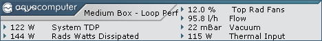
Dissipated power varies wildly with a gaming load (as shown on the dissipated power sensor) but the fan speed stays steady. But again, that's with an OCed 10900k and a 3090 on a 3 rad system.
With your 2080 with 4 huge radiators, the water temp may change a lot quicker because of the lighter load, and you will hear fan speed changes more than i do, so in your case using delay inducing items will be beneficial.
My only point was that your sensor is not universally relevant, not that it's bad and yes i still plan on testing it!
As for pump flow, there's no chance you have any kind of laminar flow in a PC loop. As soon as you have bends, it's gone' and that's basically what you have in every waterblock. Unless you run extremely low speeds which will cause thermal issues, you will always have turbulent flow, all across the loop.
On all my testing, i never found any performance benefit from changing pump speed. It is purely a function of the efficiency of your waterblocks.
If you use a crappy corsair block, there will be tons of benefits from accelerating flow under load. With better cooling blocks, it won't matter.
I personally have a pump curve, driven by delta T which is there purely to limit bubbles buildup in the rad end tanks by varying the flow a bit, but in terms of temperatures it does nothing.
and it should react to change of loads. No need to keep the fans at high speed if load reduces, or delay acceleration when load increases. I feel you are used to the delays introduced in your sensor. Adding an averaging to a delta T sensor will have the same effect with 80% less items in the sensor :pOn mine i have a 10s averaging to filter out sensor imprecisions, and it reacts very quickly to load increases.
Dissipated power varies wildly with a gaming load (as shown on the dissipated power sensor) but the fan speed stays steady. But again, that's with an OCed 10900k and a 3090 on a 3 rad system.
With your 2080 with 4 huge radiators, the water temp may change a lot quicker because of the lighter load, and you will hear fan speed changes more than i do, so in your case using delay inducing items will be beneficial.
My only point was that your sensor is not universally relevant, not that it's bad
and yes i still plan on testing it! As for pump flow, there's no chance you have any kind of laminar flow in a PC loop. As soon as you have bends, it's gone
' and that's basically what you have in every waterblock. Unless you run extremely low speeds which will cause thermal issues, you will always have turbulent flow, all across the loop.On all my testing, i never found any performance benefit from changing pump speed. It is purely a function of the efficiency of your waterblocks.
If you use a crappy corsair block, there will be tons of benefits from accelerating flow under load. With better cooling blocks, it won't matter.
I personally have a pump curve, driven by delta T which is there purely to limit bubbles buildup in the rad end tanks by varying the flow a bit, but in terms of temperatures it does nothing.
Well from the test i just ran it is extremely inefficient, i am sorry '
It's also very jumpy, which came as a surprise.
I didn't tweak the sensor besides remapping the aquaero sensors to the same ones on the Octo and attributed it to my top radiator to see some fan speed changes.
When i started loading the loop, it reacted way fast, before the water had a chance to warm up, which is basically noisy for no cooling benefit (a bit like controlling a water loop from CPU temp instead of water temp) depending on the fan curve you set. (mine is fairly gentle).
It then stops rising and flatlines while the water warms up, then starts to pick up the rise and increases to match the delta T curve. So in the end it will arrive at the same point but in huge steps instead of giving a slow steady increase, which is way more noticeable in terms of noise, and not efficient in terms of cooling since it doesn't follow the radiator efficiency increase.
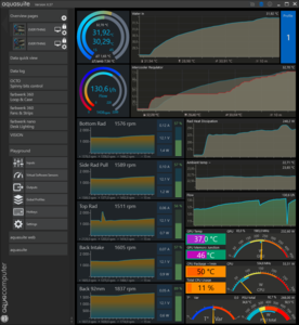
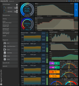
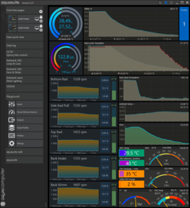
On the graphs, i've overlaid the intercooler with a red line on top of the delta T graph.
the spike in top rad speed was when setting the fan curve, disregard that
Now, when i opened my window, it was actually funny lol
The temp fell below my comfort temp setting and of course it slowed down the fans instead of cooling down the water. Silly me.
My mistake but i still fail to see what this setting is useful for, besides impeding cooling when the rads are more efficient.
And after the delta T has stabilized, the intercooler takes over 5 minutes to start responding and accelerate the fans. If i had set all my fans to that sensor, as soon as the room would have cooled, the water temp would have shot up when the fan speed drops.
When stopping the load (thanks Teams meeting for keeping the GPU boosted), the delta T cuve slows down the fans slowly, but the intercooler keeps my top rad at speed until i only hear that one.
When the sensor finally reacts, it's again pretty steep and noticeable
For all intents and purposes, it basically acts as an unstable cooling dampener, which may actually be noisier depending on how steep your fan curve is.
Adjusting the averaging times will create the same curve but more compressed in the time axis (more noticeable fan jumps).
It kind of confirms to me that the sensor really is tailored to your loop. With all the radiators (and water volume) you have, you already have some massive hysteresis and overkill cooling capacity for the load, so you may not see that very erratic behavior, or you see it but not at the same scale.
The delta between ambient and water temp being a direct reading of the radiator efficiency, i really don't see why one would not follow that curve since this is what gives you the most efficient fan curves in terms of cooling.
Edit : no offense! i may have come out a bit rough :p maybe my trial can serve as an example of how your sensor works on a smaller loop. that exacerbates the sensor responses and may show things you couldn't see on your particular loop.
'It's also very jumpy, which came as a surprise.
I didn't tweak the sensor besides remapping the aquaero sensors to the same ones on the Octo and attributed it to my top radiator to see some fan speed changes.
When i started loading the loop, it reacted way fast, before the water had a chance to warm up, which is basically noisy for no cooling benefit (a bit like controlling a water loop from CPU temp instead of water temp) depending on the fan curve you set. (mine is fairly gentle).
It then stops rising and flatlines while the water warms up, then starts to pick up the rise and increases to match the delta T curve. So in the end it will arrive at the same point but in huge steps instead of giving a slow steady increase, which is way more noticeable in terms of noise, and not efficient in terms of cooling since it doesn't follow the radiator efficiency increase.
On the graphs, i've overlaid the intercooler with a red line on top of the delta T graph.
the spike in top rad speed was when setting the fan curve, disregard that
Now, when i opened my window, it was actually funny lol
The temp fell below my comfort temp setting and of course it slowed down the fans instead of cooling down the water. Silly me.
My mistake but i still fail to see what this setting is useful for, besides impeding cooling when the rads are more efficient.
And after the delta T has stabilized, the intercooler takes over 5 minutes to start responding and accelerate the fans. If i had set all my fans to that sensor, as soon as the room would have cooled, the water temp would have shot up when the fan speed drops.
When stopping the load (thanks Teams meeting for keeping the GPU boosted), the delta T cuve slows down the fans slowly, but the intercooler keeps my top rad at speed until i only hear that one.
When the sensor finally reacts, it's again pretty steep and noticeable
For all intents and purposes, it basically acts as an unstable cooling dampener, which may actually be noisier depending on how steep your fan curve is.
Adjusting the averaging times will create the same curve but more compressed in the time axis (more noticeable fan jumps).
It kind of confirms to me that the sensor really is tailored to your loop. With all the radiators (and water volume) you have, you already have some massive hysteresis and overkill cooling capacity for the load, so you may not see that very erratic behavior, or you see it but not at the same scale.
The delta between ambient and water temp being a direct reading of the radiator efficiency, i really don't see why one would not follow that curve since this is what gives you the most efficient fan curves in terms of cooling.
Edit : no offense! i may have come out a bit rough :p maybe my trial can serve as an example of how your sensor works on a smaller loop. that exacerbates the sensor responses and may show things you couldn't see on your particular loop.
Dieser Beitrag wurde bereits 1 mal editiert, zuletzt von »Remayz« (20. September 2022, 14:43)
Remayz - What you see is the expected behavior when using component temps as the input. Component temps are very jumpy because there's no damping of not only the signal but also the actual temperature. A 50ms pause while a render moves something into memory shouldn't shut off your fans. The reason it might appear to work for pumps is exactly what you said above: the pump speed doesn't really matter.
This really is a Rube Goldberg. What the virtual sensor does is take a few approaches to damping data sources in order to "smoothly" hit a nominal cooling value with minimal undershoot and overshoot. There is value in creating a virtual instrument like this, but not in a system which has actual PID controllers. A PID will do the same thing, but much more easily, much more smoothly, and much more effectively.
If the OP is looking to burn some time, he should just manually tune the PID values instead.
the intercooler sensor doesn't use components temps, only water and ambient. but somehow it reacts very fast to a first increase of temperature, but then it shelves and doesn't accelerate the fans any further while the water heats up, then it releases and climbs a second time very fast again, this time following the increase of temps.
That's why i called it unstable, because it behaves illogically by preventing the fans from accelerating while the water temp is clearly climbing fast, and at the same time being noisier by causing fast fan accelerations when the dampening expires.
If i was to tweak the fan response without using PID, i would probably rather use the X=trend module to tweak the fan curve response based on how fast the temperature of the water increases or decreases.
If changes are slow, keep fan speed dampening long. The load may change or stop.. then you would have had no fan speed change = particularely silent.
If the temp increases very fast, like starting to play a game or a power intensive workload, then cut the dampening and accelerate right away to cool down the loop.
But as you said, tweaking PID achieves the same. But it could be cool to try to do that in a virtual sensor as a fun experiment.
In the end even if this sensor isn't my cup of tea, it must have been pretty fun to develop
@Teknophage, I just saw your fan curve when using delta T as control variable.
If it is that jumpy you have some sensor problems. Look at the curve i get, it's completely smooth, and i only use a 10 second averaging on both water and ambient temps to filter out noise in the reading in the decimals.
If your temp reading are unstable, there may be something off with the sensor itself or where the ambient one is installed
Dieser Beitrag wurde bereits 1 mal editiert, zuletzt von »Remayz« (20. September 2022, 17:52)
@Remayz: Thanks for the useful information! I was able to identify that there is a problem with one of the functions which would cause the problem you're seeing in smaller loops. A couple of points of note were that the jumpiness you saw may be due to that. I'm reviewing and running some tests to see what I can do about that. I'll update you once I have more information. On the note about the jumpy Delta-T in my situation, it's likely due to the larger loop, but I'll investigate the sensors (thermal sensor fitting + MPS400's thermal sensor).
 UPDATE: I found a bug. On the Intercooler Regulator -- Trace from Coolant (Hot) to "X=min(t)" to the 1st additive, input B. That's the problem. Replace connection with the output of X=peak(t) to input B of the 1st additive. Let me know if that helped. I'm still reviewing what you sent and running tests.
@cptninc: This is directed to help people who don't know what PIDs are or how to properly "tweak" them, or where such "tweaks" may require continuous tweaking given their environment and changes to that environment. You're deliberately being insulting.
@all: Interesting note, this is akin to a virtual PID controller. I will review the configuration and see if there's a path to align it a bit more with the way a real PID controller works.
UPDATE: I found a bug. On the Intercooler Regulator -- Trace from Coolant (Hot) to "X=min(t)" to the 1st additive, input B. That's the problem. Replace connection with the output of X=peak(t) to input B of the 1st additive. Let me know if that helped. I'm still reviewing what you sent and running tests.@cptninc: This is directed to help people who don't know what PIDs are or how to properly "tweak" them, or where such "tweaks" may require continuous tweaking given their environment and changes to that environment. You're deliberately being insulting.
@all: Interesting note, this is akin to a virtual PID controller. I will review the configuration and see if there's a path to align it a bit more with the way a real PID controller works.
the intercooler sensor doesn't use components temps, only water and ambient. but somehow it reacts very fast to a first increase of temperature, but then it shelves and doesn't accelerate the fans any further while the water heats up, then it releases and climbs a second time very fast again, this time following the increase of temps.
That's why i called it unstable, because it behaves illogically by preventing the fans from accelerating while the water temp is clearly climbing fast, and at the same time being noisier by causing fast fan accelerations when the dampening expires.
If i was to tweak the fan response without using PID, i would probably rather use the X=trend module to tweak the fan curve response based on how fast the temperature of the water increases or decreases.
If changes are slow, keep fan speed dampening long. The load may change or stop.. then you would have had no fan speed change = particularely silent.
If the temp increases very fast, like starting to play a game or a power intensive workload, then cut the dampening and accelerate right away to cool down the loop.
But as you said, tweaking PID achieves the same. But it could be cool to try to do that in a virtual sensor as a fun experiment.
In the end even if this sensor isn't my cup of tea, it must have been pretty fun to develop
@Teknophage, I just saw your fan curve when using delta T as control variable.
If it is that jumpy you have some sensor problems. Look at the curve i get, it's completely smooth, and i only use a 10 second averaging on both water and ambient temps to filter out noise in the reading in the decimals.
If your temp reading are unstable, there may be something off with the sensor itself or where the ambient one is installed
Dieser Beitrag wurde bereits 7 mal editiert, zuletzt von »Teknophage« (2. Oktober 2022, 22:03)
Delta T sensor is actually more stable in a big loop since you have more water, more thermal mass, bigger hysteresis.
If your fan speeds move that much that quickly, either you have a dodgy sensor, or your fan curve is veeeery steep..
If your fan speeds move that much that quickly, either you have a dodgy sensor, or your fan curve is veeeery steep..
@Remayz: On the note about the jumpy Delta-T in my situation, it's likely due to the larger loop, but I'll investigate the sensors (thermal sensor fitting + MPS400's thermal sensor).
@cptninc: This is directed to help people who don't know what PIDs are or how to properly "tweak" them, or where such "tweaks" may require continuous tweaking given their environment and changes to that environment. You're deliberately being insulting.
One of the great things about Aquacomputer's controllers is that, just like you, the end user doesn't even have to know what a PID is in order to use them. Just pick a target temp and then decide how quickly you want the system to respond. That's it. No need to spend five years tweaking things in order to get a solution that works 80% of the time.
One of the great things about PIDs is that constant tweaking is NOT required. In fact, that's the whole point of them. And, BTW, what exactly are you doing? You're two years into this, you're still tweaking, still fixing bugs, and you even said yourself that you even have to retweak things for every change of season.
It was probably smart of you to edit out your original statement about how this isn't a Rube Goldberg device given your closing statement about how you're trying to make this a needlessly complex alternative to the pre-tuned PID controllers that are built into the Aquacomputer ecosystem.
@Remayz - The Intercooler Regulator has been redesigned, thanks to your information.
Montag, 3. Oktober 2022, 03:57
I'm thankful for the information you supplied. I was able to identify a better approach. Using the X=trend as you recommended, I came up with a better formula that better fits expected behavior. What cptninc is describing as a built-in PID is really just the controller itself. While simple, yes, it does not have a self-corrective feedback loop. They have more in common with a household thermostat than an electromechanical PID device. They can't estimate how much corrective action to implement based upon a weighted additive.
The new design resolves a few noted issues: Chiefly the lag you experienced. By using the trend as recommended, it provides gain to the average between high and low over the past five minutes. To answer the question about set points, the set point is the average between the high and the low over five minutes. That explains the initial jump you saw, but because there was no gain function, it held there until sufficient heat had registered. That was a problem that escaped me.
The differential between average ambient temperature and the present temperature of the hot is better accounted for and multiplied against the integral. This is as close to the Ziegler-Nichols method of the PID formula as possible, while eliminating a hard set point. You'll note that the ambient temperatures are now auto-averaged. There's still a place called "Set Point" which is intended for setting one's comfortable room temperature. This one is set by default to 72F. Anything lower than this is taken to use as the set point. Anything lower is the average of the room's daily day/night high/low cycle. I put that in there really as an override if the room gets too hot.
Aside from these changes, I've removed the rounder. Give this one a try: Thermal and Intercooler Regulators.zip


As mentioned, the whole idea to bring this out to others is to help others and gather input to improve it.
The new design resolves a few noted issues: Chiefly the lag you experienced. By using the trend as recommended, it provides gain to the average between high and low over the past five minutes. To answer the question about set points, the set point is the average between the high and the low over five minutes. That explains the initial jump you saw, but because there was no gain function, it held there until sufficient heat had registered. That was a problem that escaped me.
The differential between average ambient temperature and the present temperature of the hot is better accounted for and multiplied against the integral. This is as close to the Ziegler-Nichols method of the PID formula as possible, while eliminating a hard set point. You'll note that the ambient temperatures are now auto-averaged. There's still a place called "Set Point" which is intended for setting one's comfortable room temperature. This one is set by default to 72F. Anything lower than this is taken to use as the set point. Anything lower is the average of the room's daily day/night high/low cycle. I put that in there really as an override if the room gets too hot.
Aside from these changes, I've removed the rounder. Give this one a try: Thermal and Intercooler Regulators.zip
As mentioned, the whole idea to bring this out to others is to help others and gather input to improve it.
Dieser Beitrag wurde bereits 2 mal editiert, zuletzt von »Teknophage« (3. Oktober 2022, 04:14)
What is that blue "Intake" sensor? fan speed or temperature?
It looks unstable AF. I still feel if your sensors were stable you wouldn't even need to bother with overcomplicated sensors to try to find a useful signal out of that noise'
If it's a fan speed.. same deal, teh readouts on my octo are dead stable.
Temp sensors see variations only at the second decimal, and still, on water it's like -+0.01°C . This is what i am smoothing with that 10sec averaging.
It looks unstable AF. I still feel if your sensors were stable you wouldn't even need to bother with overcomplicated sensors to try to find a useful signal out of that noise
'If it's a fan speed.. same deal, teh readouts on my octo are dead stable.
Temp sensors see variations only at the second decimal, and still, on water it's like -+0.01°C . This is what i am smoothing with that 10sec averaging.
RE: @Remayz - The Intercooler Regulator has been redesigned, thanks to your information.
Montag, 3. Oktober 2022, 13:51
What cptninc is describing as a built-in PID is really just the controller itself. While simple, yes, it does not have a self-corrective feedback loop. They have more in common with a household thermostat than an electromechanical PID device. They can't estimate how much corrective action to implement based upon a weighted additive.
No. What I am describing is, literally, a PID controller. A PID loop literally is "a self-corrective feedback loop." The various Aquacomputer devices which allow setpoint controllers, again, literally, use PID controllers for that. If you don't like the 5 preset tunes, you can even go to "Custom" and enter new values yourself.
Ähnliche Themen
-
 English forum »
-
 D5 Pump Speeds
(27. Juli 2022, 10:04)
D5 Pump Speeds
(27. Juli 2022, 10:04)
-
- English forum »
-
Leakshield and kryographics next rtx 2080 ti: pressure drops when GPU heats
(13. August 2021, 15:47)
-
- English forum »
-
MPS 400 flow meter durability
(28. Dezember 2016, 16:39)
-
- English forum »
-
VRM cooling blocks for ASUS A8N series
(26. Oktober 2005, 16:41)
-
- Off-Topic »
-
Katzenbabys - 10 1/2 Wochen S. 25
(8. November 2003, 07:38)
-