 24.04.2024, 17:00
 Sprache ändern
 Registrieren
 Anmelden
Sie sind nicht angemeldet.
Lieber Besucher, herzlich willkommen bei: Aqua Computer Forum. Falls dies Ihr erster Besuch auf dieser Seite ist, lesen Sie sich bitte die Hilfe durch. Dort wird Ihnen die Bedienung dieser Seite näher erläutert. Darüber hinaus sollten Sie sich registrieren, um alle Funktionen dieser Seite nutzen zu können. Benutzen Sie das Registrierungsformular, um sich zu registrieren oder informieren Sie sich ausführlich über den Registrierungsvorgang. Falls Sie sich bereits zu einem früheren Zeitpunkt registriert haben, können Sie sich hier anmelden.

That's brilliant thank, you so much, that's really helpful. :thumbsup:
One thing I read, I think on reddit...?...is that because of how the High Flow Next's temp sensor is recessed deep in the unit, it adds 2 degrees Celsius to the actual coolant temperature? I'm reluctant to use its inbuilt temp sensor for that reason?
I'm trying to find the post...I'll see if I can post a link.
Edit: It was in this thread: high flow NEXT - The next generation of flow sensors
The High Flow Next's temp sensor is 1 to 2 degrees Centigrade off?
Due to the proximity of the sensor to the High Flow NEXT's electronics, there is a bias of 2° to 3° introduced when there is NO flow in the loop. When there is flow in the loop the bias is overwhelmed and the internal temperature sensor appears to read correctly. (discussed HERE)
The product page for the High Flow NEXT states"
Which leads me to believe it is similar in capability to a Calitemp, and I would give it more credence than a standard temperature sensor in the loop.
Zitat
Sensor for coolant temperature
The high flow NEXT is equipped with a very precise and fast water temperature sensor.
Oh, okay...that's really interesting; it's my first custom loop and all of it is very new to me...it hadn't even occurred to me to take account of ambient temperature when setting fan speeds.for fan control based on temperature delta you want it to be the delta between water and ambient temperature (so, add a sensor that you'll leave dangling off the case out of sight).
That allows your fans to adapt their speed no matter what the temp is in your room.
Having two inline sensors, and a flow sensor allows you to measure real dissipated power in your loop. that's not exactly useful but a fun reading to have
the only catch is that you have to have your radiators in series (no waterblock in between rads), one sensor before, one sensor after.
With flow, temperature delta between inlet and outlet, and the water specific heat value, you can create a virtual sensor to display the power dissipated in watts in real time.

...is there a 'rule of thumb' / general rule for how far apart the temps need to be (ambient & coolant) ? I'm finding it a little difficult to imagine how it would be done.
Also, yes, I was thinking it would be fun to see the temperature differential before and after the radiators. Is the calculation for measuring dissipated power built into the software, or is it something that's user configured? I've no idea how I'd go about doing that.
Also, I'm not going to have waterblocks in between my rads but they aren't all in series...?...I'm putting a 140mm rad in the floor of my case between the pump/reservoir combo and the GPU...so the order will be:
Reservoir -> Pump -> Radiator -> GPU -> CPU -> Radiator -> Radiator -> and back to the reservoir. I'm intending to measure coolant temp after GPU/CPU, before the first radiator. I'll probably add the High Flow Next after the pump and before the 140mm rad in the floor of the case.
Dieser Beitrag wurde bereits 2 mal editiert, zuletzt von »P.C.Zen« (30. August 2021, 13:35)
Apologies for the double post but I almost missed this response because the page rolled over...
...and you really think it's more precise than the Aquacomputer inline temp sensor (model 50367)?
If so, then I should benefit from adding the High Flow Next into the loop after my GPU/CPU and before the first radiator? I'm guessing that's the best place to take the coolent temperature measurement?
Also, how much more accurate would High Flow Next be? I'm guessing the basic inline temp sensors should already be pretty accurate?
Awesome, thanks so much, that's brilliant news...That's brilliant thank, you so much, that's really helpful.
One thing I read, I think on reddit...?...is that because of how the High Flow Next's temp sensor is recessed deep in the unit, it adds 2 degrees Celsius to the actual coolant temperature? I'm reluctant to use its inbuilt temp sensor for that reason?
I'm trying to find the post...I'll see if I can post a link.
Edit: It was in this thread: high flow NEXT - The next generation of flow sensors
The High Flow Next's temp sensor is 1 to 2 degrees Centigrade off?
Due to the proximity of the sensor to the High Flow NEXT's electronics, there is a bias of 2° to 3° introduced when there is NO flow in the loop. When there is flow in the loop the bias is overwhelmed and the internal temperature sensor appears to read correctly. (discussed HERE)
The product page for the High Flow NEXT states"
Which leads me to believe it is similar in capability to a Calitemp, and I would give it more credence than a standard temperature sensor in the loop.
Sensor for coolant temperature
The high flow NEXT is equipped with a very precise and fast water temperature sensor.
...and you really think it's more precise than the Aquacomputer inline temp sensor (model 50367)?
If so, then I should benefit from adding the High Flow Next into the loop after my GPU/CPU and before the first radiator? I'm guessing that's the best place to take the coolent temperature measurement?
Also, how much more accurate would High Flow Next be? I'm guessing the basic inline temp sensors should already be pretty accurate?
Dieser Beitrag wurde bereits 3 mal editiert, zuletzt von »P.C.Zen« (30. August 2021, 13:56)
power dissipation is a virtual sensor that you make yourself. you can find the formula to calculate dissipated power for liquid cooling circuits and just adapt it (mostly converting units really and doing simple maths).
we have flow in L/h, specific heat in joules per Kelvin per kilogram, temp delta in °C (one °C being equal to 1 kelvin, we leave it as is), and watts are joules per second.. so you have to convert all to SI units (flow from L.h to kg/s)
then it's just a matter of multiplying everything, flow (kg/s) x water specific heat (J.K.kg) x delta t (°C) = dissipated power in joules/sec, or Watts.
that's the virtual sensor i use for it :
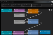
There's a separate virtual sensor just for the delta T, because i need it to make the display of that temperature on the dashboard.
The purple bits are just low pass filters to filter the sensor readings, making them more stable (makes a prettier curve, less spiky :p)
As for the delta temp between ambient and water, you'll probably figure it out just looking at the temperatures and the noise your fans make depends from setup to setup.
For me i have the fan curve as a straight line, 27% PWM at 1.5°C for the slowest speed, and 85% PWM at 15°C.
Typically, under load, the delta T will stay around 9 or 10° somewhere around 60% PWM in the curve.
Radiators are more efficient as the delta increases so the speed will self regulate as water temp goes up.
Why ambient is nice to take into account is, if for example you're in the middle of a heatwave, your room is at 35°; water sits at 38, and your fan curve you had set a month prior has fans at 80% for that temp, they will go fast for nothing, because the air is too warm. Temperature will drop so little it's worthless.
Corrected for ambient temp, they would accelerate only if there's real load on the loop. In that example, water can't go below ambient, so there's no point in ramping up speed since the radiators can't dissipate much, since the delta is too small.
In short, it will make the fans ramp up only when needed, wether your room is hot or cold.
Now if you have AC in the room and it's the same temp all year long, you probably don't need to bother
we have flow in L/h, specific heat in joules per Kelvin per kilogram, temp delta in °C (one °C being equal to 1 kelvin, we leave it as is), and watts are joules per second.. so you have to convert all to SI units (flow from L.h to kg/s)
then it's just a matter of multiplying everything, flow (kg/s) x water specific heat (J.K.kg) x delta t (°C) = dissipated power in joules/sec, or Watts.
that's the virtual sensor i use for it :
There's a separate virtual sensor just for the delta T, because i need it to make the display of that temperature on the dashboard.
The purple bits are just low pass filters to filter the sensor readings, making them more stable (makes a prettier curve, less spiky :p)
As for the delta temp between ambient and water, you'll probably figure it out just looking at the temperatures and the noise your fans make
depends from setup to setup.For me i have the fan curve as a straight line, 27% PWM at 1.5°C for the slowest speed, and 85% PWM at 15°C.
Typically, under load, the delta T will stay around 9 or 10° somewhere around 60% PWM in the curve.
Radiators are more efficient as the delta increases so the speed will self regulate as water temp goes up.
Why ambient is nice to take into account is, if for example you're in the middle of a heatwave, your room is at 35°; water sits at 38, and your fan curve you had set a month prior has fans at 80% for that temp, they will go fast for nothing, because the air is too warm. Temperature will drop so little it's worthless.
Corrected for ambient temp, they would accelerate only if there's real load on the loop. In that example, water can't go below ambient, so there's no point in ramping up speed since the radiators can't dissipate much, since the delta is too small.
In short, it will make the fans ramp up only when needed, wether your room is hot or cold.
Now if you have AC in the room and it's the same temp all year long, you probably don't need to bother
The virtual sensor for heat dissipation looks really complex to me...I'm trying to get my head around it but I think I might need to re-read it a few times. Were I just to copy what you've created there would it work?power dissipation is a virtual sensor that you make yourself. you can find the formula to calculate dissipated power for liquid cooling circuits and just adapt it (mostly converting units really and doing simple maths).
we have flow in L/h, specific heat in joules per Kelvin per kilogram, temp delta in °C (one °C being equal to 1 kelvin, we leave it as is), and watts are joules per second.. so you have to convert all to SI units (flow from L.h to kg/s)
then it's just a matter of multiplying everything, flow (kg/s) x water specific heat (J.K.kg) x delta t (°C) = dissipated power in joules/sec, or Watts.
that's the virtual sensor i use for it :
There's a separate virtual sensor just for the delta T, because i need it to make the display of that temperature on the dashboard.
The purple bits are just low pass filters to filter the sensor readings, making them more stable (makes a prettier curve, less spiky :p)
As for the delta temp between ambient and water, you'll probably figure it out just looking at the temperatures and the noise your fans make
For me i have the fan curve as a straight line, 27% PWM at 1.5°C for the slowest speed, and 85% PWM at 15°C.
Typically, under load, the delta T will stay around 9 or 10° somewhere around 60% PWM in the curve.
Radiators are more efficient as the delta increases so the speed will self regulate as water temp goes up.
Why ambient is nice to take into account is, if for example you're in the middle of a heatwave, your room is at 35°; water sits at 38, and your fan curve you had set a month prior has fans at 80% for that temp, they will go fast for nothing, because the air is too warm. Temperature will drop so little it's worthless.
Corrected for ambient temp, they would accelerate only if there's real load on the loop. In that example, water can't go below ambient, so there's no point in ramping up speed since the radiators can't dissipate much, since the delta is too small.
In short, it will make the fans ramp up only when needed, wether your room is hot or cold.
Now if you have AC in the room and it's the same temp all year long, you probably don't need to bother
I was thinking it might be cool to calculate heat dissipation for each radiator but looking at the formula I think I'd be lucky just to be able to get that working for my entire loop as a whole.

Edit: How does the low pass filter work? It doesn't look like it's really doing anything other than renaming the value...?
Edit: To be honest I think I'd need a primer just to understand the terminology...I don't have the foundation of knowledge to really understand it.

Dieser Beitrag wurde bereits 2 mal editiert, zuletzt von »P.C.Zen« (30. August 2021, 14:32)
Awesome, thanks so much, that's brilliant news...
...and you really think it's more precise than the Aquacomputer inline temp sensor (model 50367)?
If so, then I should benefit from adding the High Flow Next into the loop after my GPU/CPU and before the first radiator? I'm guessing that's the best place to take the coolent temperature measurement?
Also, how much more accurate would High Flow Next be? I'm guessing the basic inline temp sensors should already be pretty accurate?
I did not find a part number 50367, but absolute accuracy is not as important as both temperature sensors having the same offset. The High Flow NEXT temperature sensor is fine, if not great.
As for power dissipation across a radiator set, the High Flow NEXT has a builtin function for that (power.jpg), but don't use the 'Automatic offset compensation in standby'.
The only requirement is that the 2nd sensor (one of THESE) be connected to the external temp input on the Flow NEXT.
Thanks,Awesome, thanks so much, that's brilliant news...
...and you really think it's more precise than the Aquacomputer inline temp sensor (model 50367)?
If so, then I should benefit from adding the High Flow Next into the loop after my GPU/CPU and before the first radiator? I'm guessing that's the best place to take the coolent temperature measurement?
Also, how much more accurate would High Flow Next be? I'm guessing the basic inline temp sensors should already be pretty accurate?
I did not find a part number 50367, but absolute accuracy is not as important as both temperature sensors having the same offset. The High Flow NEXT temperature sensor is fine, if not great.
As for power dissipation across a radiator set, the High Flow NEXT has a builtin function for that ([attach]8731[/attach]), but don't use the 'Automatic offset compensation in standby'.
The only requirement is that the 2nd sensor (one of THESE) be connected to the external temp input on the Flow NEXT.
 And it doesn't need to know the volume of water in the loop?
Also, I'm not sure exactly what's meant by 'offset'? I'm guessing the ones you linked to are going to be configured correctly for use with the High Flow Next? Or is the offset something user defined in the software?
The two sensors I have on their way to me are for use with the Quadro...so...I'll be able to use that function of the software but using temperature values taken by the two temp sensors plugged into the quadro...?...is that correct? I mean, it's the same software (Aquasuite)...?
Dieser Beitrag wurde bereits 8 mal editiert, zuletzt von »P.C.Zen« (30. August 2021, 15:51)
nice about the integrated power calcualtion :p
basically aquasuite does automatically what the virtual sensor does.
Apparently, you need to have the Next at one end of the rads, and the second sensor at the other end, and that addditional sensor has to be connected directly to the Next, not to the Quadro.
They are the same sensors anyway, so you can plug one that you bought. they are all 10kohm NTC thermistors.
The quantity of water is irrelevant. the only thing needed is to know how much water passes every second. The temperature delta allows to calculate how much energy has been taken out of the water to reduce its temperature. (that's the reading in W).
You can have 500ml, 2 liters, doesn't matter.
Thanksnice about the integrated power calcualtion :p
basically aquasuite does automatically what the virtual sensor does.
Apparently, you need to have the Next at one end of the rads, and the second sensor at the other end, and that addditional sensor has to be connected directly to the Next, not to the Quadro.
They are the same sensors anyway, so you can plug one that you bought. they are all 10kohm NTC thermistors.
The quantity of water is irrelevant. the only thing needed is to know how much water passes every second. The temperature delta allows to calculate how much energy has been taken out of the water to reduce its temperature. (that's the reading in W).
You can have 500ml, 2 liters, doesn't matter.

Although I think the connectors on the temp sensors differ, so they're not compatible with the High Flow Next, for that reason?
Will I be able to measure power dissipation and configure an offset between ambient and coolant temperature using the High Flow Next and one compatible sensor...?...the reason I ask is because I think I may not need the temperature sensors I ordered for the Quadro, if I can?
Edit: Okay, so...I cancelled my Amazon order for the 2 Quadro temp sensors...can I basically set the ambient:coolant delta & measure power dissipation using just the High Flow Next and its compatible temp sensor...?...I hope that's a yes because I just ordered a High Flow Next compatible temp sensor.

Edit:
 Okay, so...no: I can't set a delta using just the High Flow Next because I need the extra sensor via the Quadro to measure ambient temperature, because the High Flow Next only has one temp sensor input.
 Dieser Beitrag wurde bereits 5 mal editiert, zuletzt von »P.C.Zen« (30. August 2021, 16:56)
one of the two has the same connector as all those on the market. the one not in stock has the picoblade connector required for the high flow next.
for the room temperature obviously you'll need another sensor going to the quadro, but you should receive one in the package
you are not stuck using sensors only for one function. You can use the inline sensors for power dissipation, and also to calculate delta T for fan control. But everything will be easier when you'll be in front of Aquasuite, clicking away to see all it can do.
In the Playground, you create virtual sensors from real sensors, with various operations.
"NEXT temp sensor" - "ambient temp" = "dT temperature"
in the Quadro sensor page, you have empty software sensors. You use one of those slots to add the sensor you just created, and then the dT temperature is available on the Quadro to create fan curves.
Dieser Beitrag wurde bereits 2 mal editiert, zuletzt von »Remayz« (30. August 2021, 19:17)
Wow thanks...that pretty much clarifies things for me.one of the two has the same connector as all those on the market. the one not in stock has the picoblade connector required for the high flow next.
for the room temperature obviously you'll need another sensor going to the quadro, but you should receive one in the package
you are not stuck using sensors only for one function. You can use the inline sensors for power dissipation, and also to calculate delta T for fan control. But everything will be easier when you'll be in front of Aquasuite, clicking away to see all it can do.
In the Playground, you create virtual sensors from real sensors, with various operations.
"NEXT temp sensor" - "ambient temp" = "dT temperature"
in the Quadro sensor page, you have empty software sensors. You use one of those slots to add the sensor you just created, and then the dT temperature is available on the Quadro to create fan curves.
I managed to find one of the 53218 temp sensors with the picoblade connector and it's on its way to me. I cancelled the order for the other two...
...I still need the Quadro for the temp sensor for the delta and to control my fans, so that's the next thing on the shopping list.
I've placed an order for a High Flow Next, so just waiting for it to come back into stock.
Thanks for the explanation re. setting the delta, it's very helpful; I'm not sure if I would have been able to figure it out on my own?
My German is... bad, but I believe you ask if it is OK for the Hight Flow next to be supported just by hardline tubing?Ich hätte eine Frage. Wenn man den High Flow Next mit Hardtubes montiert,
gibt es einen Vorteil (zum Beispiel was Geräusche anbelangt) den Sensor so zu montieren
das er von etwas unterstützt ist oder kann er ohne weiteres im Leeren nur von den
hardtubes gehaltet sein ?
Mine is - PETG 16mm on both sides.
Weder mein Deutsch noch mein English sind Gut… Ich weiss dass
bei mehrere, den High Flow nur von den Tubes gehaltet ist, ohne dass es auf etwas
liegt. Meine Frage ist aber zu wissen ob die eine oder die Andere Lösung (mit oder
ohne Unterstützung) Nachteile oder Vorteile bringt besonders was Geräusche anbelangt.
Neither my German nor my English are good…I know that many people
are mounting the High Flow Next holding it in place only by the tubing, without
any support underneath. My question is to know if the one or the other solution
(with or without support) has advantages or disavantages, especially regarding the
noise that the sensor may produce.
The only thing that could cause noise via the tubes are the vibrations of the high flow NEXT, but these can also cause noise with a mount.
So far I have never heard of resonances in connection with the high flow NEXT.
So you really only have to consider whether the fittings can hold the weight of the high flow NEXT or whether it will be too heavy.
So far I have never heard of resonances in connection with the high flow NEXT.
So you really only have to consider whether the fittings can hold the weight of the high flow NEXT or whether it will be too heavy.
Es gibt keinen Ausweg, den ein Mensch nicht beschreitet, um die tatsächliche Arbeit des Denkens zu vermeiden.
Thomas Alva Edison (1847-1931), amerik. Erfinder
Thomas Alva Edison (1847-1931), amerik. Erfinder
I just realized that I posted in the english forum and not in the german one… sorry. I will double post in the german forum too in order to get
a larger feedback.
When talking about noise, I was thinking of the tickling noise that is sometimes reported to be heard at higher flow rates (more than 100 or
150 L/h). Could supporting the High Flow next from underneath help to prevent this
inconvenience ?
What about the weight ? Are the hardtubes and the fittings sufficient to hold the weight or would it be better to use a support ?
No, the hardtubes have nothing to do with it, above a certain flow rate, which probably rather starts at more than 200 l/h, every flow sensor will click.
When talking about noise, I was thinking of the tickling noise that is
sometimes reported to be heard at higher flow rates (more than 100 or
150 L/h). Could supporting the High Flow next from underneath help to prevent this
inconvenience ?
What about the weight ? Are the hardtubes and the fittings sufficient to
hold the weight or would it be better to use a support ?
This probably depends on your tubes, fittings and installation method.
If the tubes go up from the sensor in an L shape the weight of the sensor would be fully on the fittings, if you have good fittings this should not be a problem.
If the tubes are straight you have no problem anyway.
But you should do it the way it fits and how you feel comfortable with it.
Es gibt keinen Ausweg, den ein Mensch nicht beschreitet, um die tatsächliche Arbeit des Denkens zu vermeiden.
Thomas Alva Edison (1847-1931), amerik. Erfinder
Thomas Alva Edison (1847-1931), amerik. Erfinder
Is there a minimum distance from a bend that the sensor needs to be or does it not matter?
- angled fittings induce turbulence in the flow stream
- the High Flow NEXT has an actual impeller, and accuracy is not greatly impaired with turbulence
- but turbulence may affect impeller noise (ticking) by causing shake/shimmy in the impeller
- the MPS Flow Sensor measure turbulence in the flow stream, and angled fittings greatly affect accuracy
Ähnliche Themen
-
 English forum »
-
 Two High Flow Sensors - One Aquaero 6 LT
(6. April 2020, 06:21)
Two High Flow Sensors - One Aquaero 6 LT
(6. April 2020, 06:21)
-
- English forum »
-
How to connect an Aquaero 6 PRO to a 6LT as slave. Fan control questions.
(7. April 2019, 22:52)
-
- English forum »
-
flow meter
(5. Juni 2017, 08:55)
-
- English forum »
-
Need assistance with High Flow Meter USB Setup.
(4. August 2013, 02:52)
-
- English forum »
-
aquaero5 xt
(4. August 2013, 08:56)
-