 26.04.2024, 10:58
 Sprache ändern
 Registrieren
 Anmelden
Sie sind nicht angemeldet.
Lieber Besucher, herzlich willkommen bei: Aqua Computer Forum. Falls dies Ihr erster Besuch auf dieser Seite ist, lesen Sie sich bitte die Hilfe durch. Dort wird Ihnen die Bedienung dieser Seite näher erläutert. Darüber hinaus sollten Sie sich registrieren, um alle Funktionen dieser Seite nutzen zu können. Benutzen Sie das Registrierungsformular, um sich zu registrieren oder informieren Sie sich ausführlich über den Registrierungsvorgang. Falls Sie sich bereits zu einem früheren Zeitpunkt registriert haben, können Sie sich hier anmelden.

Hi, just wondering if anyone else has seen the pictured happen to their MPS.
Its an MPS 200 that I got and fitted when they were first available so it's been in use quite a long time.
The fill level alarm on my aquaero went of this morning and I found the coolant leaking out through one of the small holes on the back.
Got another one on order to replace it already and I'm just pleased the alarm alerted it to me before any other damage happened.
PS. Excuse the dust in the pic! IMG_20170429_102242-1856x1044.jpg
Looks like there may have been some stress on the connection between the fitting and the MPS200.
The tube on the left out of the Tee Block looks lower than the tube on the inlet side of the MPS 200.
That is forcing a slope between the two tube sections that is causing the fittings to stress.
The MPS 400 inlet fitting appears to have more space on the bottom than the top, i.e. not a square fit.
This pressure may have caused a failure in the MPS 200 housing over time.
You may consider modifying the tubing a bit on the refit.
Yeah, I knew having the MPS and a valve only supported by the pipes was going to end up giving trouble and always planned to get back to it but never did.
The fittings are fine though and are square, it probably just was the fact it's only held up by the pipes.
I was expecting the £5 fittings to fail and/or the pipe work to work loose from the fittings not a £50 sensor from Aquacomputer.
When my new one arrives I'll have to build up some kind of support underneath it. I should really rework the pipes and put them both closer to a radiator or something more solid than in the middle of a stretch of pipe but that will have to wait for a while as got zero supplies as haven't done any building or nodding since I built this one.
Still it lasted 3.5 years so can't really complain too much.
So it looks like your internal sensor gasket is leaking.
When they do leak its normally when new and a result of the gasket being installed improperly. In this case either the gasket has moved due to pressure change cycles or it has failed.
You need to open it up and check the rubber gasket that fits on the sensor probes. If its intact you might be able to reseat it and carry on but its possible that it needs replacing.
Aquacomp support can send you a new one.
 [/URL][/img]
There is a very particular method needed to install the gasket without leaking. It should be placed on the sensor prongs outside of the housing and the whole PCB inserted back in.
The gasket should be inserted to the housing first and the sensor board slid into the gasket gently just enough so that the metal standoff screw can be inserted. The screw is then putting pressure on the back of the board and forcing the sensor prongs against the gasket. When its installed properly you should be able to see that the gasket is being squashed a little. If not the prongs may have slipped in too far.
I recommend looking at the overclock.net community testing thread for more details
When they do leak its normally when new and a result of the gasket being installed improperly. In this case either the gasket has moved due to pressure change cycles or it has failed.
You need to open it up and check the rubber gasket that fits on the sensor probes. If its intact you might be able to reseat it and carry on but its possible that it needs replacing.
Aquacomp support can send you a new one.
[/URL][/img]There is a very particular method needed to install the gasket without leaking. It should be placed on the sensor prongs outside of the housing and the whole PCB inserted back in.
The gasket should be inserted to the housing first and the sensor board slid into the gasket gently just enough so that the metal standoff screw can be inserted. The screw is then putting pressure on the back of the board and forcing the sensor prongs against the gasket. When its installed properly you should be able to see that the gasket is being squashed a little. If not the prongs may have slipped in too far.
I recommend looking at the overclock.net community testing thread for more details
Dieser Beitrag wurde bereits 3 mal editiert, zuletzt von »Jakusonfire« (17. Mai 2017, 13:59)

It looks like soft tubing, there is no way it should create enough stress to MPS internals unless pulled out and fittings itself had to handle way more stress than that...Looks like there may have been some stress on the connection between the fitting and the MPS200.
The tube on the left out of the Tee Block looks lower than the tube on the inlet side of the MPS 200.
That is forcing a slope between the two tube sections that is causing the fittings to stress.
The MPS 400 inlet fitting appears to have more space on the bottom than the top, i.e. not a square fit.
This pressure may have caused a failure in the MPS 200 housing over time.
You may consider modifying the tubing a bit on the refit.
It looks like soft tubing, there is no way it should create enough stress to MPS internals unless pulled out and fittings itself had to handle way more stress than that...
The op can clear this up for us, but to me it sure looks like two hard line sections with a distinct difference in elevation between the two ends.
There is a very particular method needed to install the gasket without leaking. It should be placed on the sensor prongs outside of the housing and the whole PCB inserted back in.
I recommend looking at the overclock.net community testing thread for more details
I am looking at this gasket on my MPS pressure sensor atm, and the reassembly instructions provided by Shoggy varies a bit as to the order of things.
A snippet from the email sent me:
Zitat
You could remove the stainless steel cover of the sensor, remove the screw on the inside and pull out the sensor board sidewards. There is a gasket that covers the two nozzles of the black sensor head. Remove it and check that the gasket and nozzles are clean. When you assemble it again, push the gasket in the case and not onto the nozzles first because it is likely that if you pull them too much over the nozzles, there will be no proper contact to the holes in the case. Just let the nozzles do the job when you slide in the sensor board again.
Dieser Beitrag wurde bereits 1 mal editiert, zuletzt von »InfoSeeker« (4. Mai 2017, 16:39)
Hi,
Apologies been slow to reply. Works been crazy.
Its hard acrylic pipes.
The trouble is the length of the pipe on the left is about 20cm long and so the weight of the T, drain valve and MPS all at the same point causes it to sag which must have caused the pressure for the leak.
My new MPS should arrive today. I'm going to see if I have spare fittings/pipe to split them up and try to position them in a stronger position, although that was the only place I had for the drain at the lowest pipework.
There is a very particular method needed to install the gasket without leaking. It should be placed on the sensor prongs outside of the housing and the whole PCB inserted back in.
I recommend looking at the overclock.net community testing thread for more details
I am looking at this gasket on my MPS pressure sensor atm, and the reassembly instructions provided by Shoggy varies a bit as to the order of things.
A snippet from the email sent me:
You could remove the stainless steel cover of the sensor, remove the screw on the inside and pull out the sensor board sidewards. There is a gasket that covers the two nozzles of the black sensor head. Remove it and check that the gasket and nozzles are clean. When you assemble it again, push the gasket in the case and not onto the nozzles first because it is likely that if you pull them too much over the nozzles, there will be no proper contact to the holes in the case. Just let the nozzles do the job when you slide in the sensor board again.
That's correct. I got mixed up because I was just going from memory. I knew it was easy for the prongs to be pushed too far into the gasket using one of the techniques because it caused me problems and I had to do it many times before I worked it out, but misremebered which one. This was back before we had any instructions from support.
The proper method is detailed in the Overclock.net community testing thread I mentioned though.
http://www.overclock.net/t/1501978/ocn-c…0#post_22678032
The coolant leaking out of the small holes in the back of the sensor is definitely a gasket leak though. The fittings might stress the threads but they aren't connected to the internals where the small screw holes are. Water there can only come through the gasket.
Dieser Beitrag wurde bereits 3 mal editiert, zuletzt von »Jakusonfire« (17. Mai 2017, 13:56)
[snip]
The coolant leaking out of the small holes in the back of the sensor is definitely a gasket leak though. The fittings might stress the threads but they aren't connected to the internals where the small screw holes are. Water there can only come through the gasket.
@jakusonfire please, I am not being argumentative, just trying to understand the issue...
In examining the case of my MPS flow 400, the holes on the backside appear to be for mounting the device to a support bracket... they do not penetrate into the cavity where the electronics and the gasket sits. So even were the cavity full of fluid, it would not have a path to leak out those mounting holes on the back, unless there were a crack in the case between the cavity & the mounting holes.
And since it appears the electronics module is still functioning (failure was not expressed in op), it may also be a crack in the case between the main flow path and the mounting holes.
Hopefully @gahlaktus will have time to tell us what he finds after he replaces the MPS flow 200 in his rig.
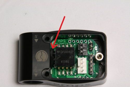
The holes do go all the way into the electronics cavity.
The single top one is where the metal standoff mounts that holds the sensor board in place. The bottom right one, the one leaking in the OP's pic is connected to a slot that the sensor board fits into. Its not a large hole but its big enough. It is only sealed by the PCB being wedged into fairly loosely
Here is a pic of the mps 400 with a light in the sensor cavity
 [/URL][/img]
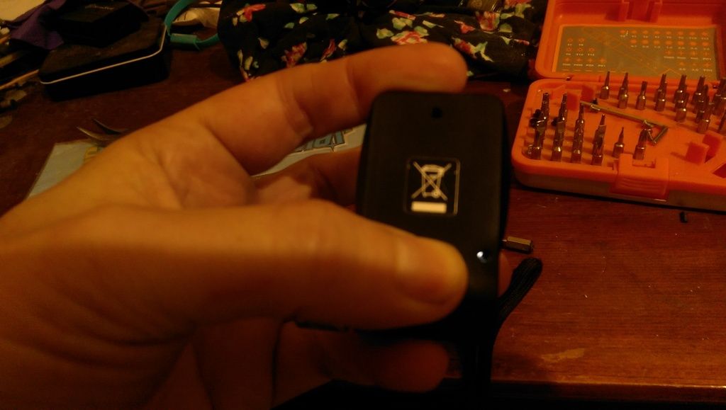
I don't make this stuff up. As I talked about before this isn't a new thing. It has happened plenty of times before.
MPS400 DOA
Acetal does not crack like acrylic does. It is very soft in comparison so any crack would be far more likely to split the whole case apart rather than just connecting internal areas without external signs
Dieser Beitrag wurde bereits 7 mal editiert, zuletzt von »Jakusonfire« (30. Mai 2017, 18:21)
Maybe a tolerance issue in manufacturing. The mounting screw holes and the face plate holding holes are in close proximity and, maybe they interconnect sometimes.
I know the gasket at the ports is capable of leaking, so that may be the source.
My unit does not show any light leaking between the two sets of bores.
I hope the OP will have time to update us with his findings after replacing the unit.
I know the gasket at the ports is capable of leaking, so that may be the source.
My unit does not show any light leaking between the two sets of bores.
I hope the OP will have time to update us with his findings after replacing the unit.
It's not the front and rear threaded holes meeting. They are offset from each other and too shallow to connect.
Like I said, it's a slot for the pcb that keeps the front end of the pcb held flat.
I have 3 mps sensors and they are all the same, this isn't a manufacturing mistake.
Like I said, it's a slot for the pcb that keeps the front end of the pcb held flat.
I have 3 mps sensors and they are all the same, this isn't a manufacturing mistake.
Dieser Beitrag wurde bereits 1 mal editiert, zuletzt von »Jakusonfire« (31. Mai 2017, 03:26)
Ähnliche Themen
-
 English forum »
-
 Res with d5 base leaking! please help
(22. Oktober 2016, 23:42)
Res with d5 base leaking! please help
(22. Oktober 2016, 23:42)
-
- English forum »
-
which flow sensor should i get?
(23. Januar 2014, 23:20)
-
- English forum »
-
leaking water temperatur sensor with temperatures above 100C
(25. Oktober 2013, 17:04)
-
- English forum »
-
Leaking Problems
(5. Dezember 2007, 01:35)
-