 26.04.2024, 16:51
 Sprache ändern
 Registrieren
 Anmelden
Sie sind nicht angemeldet.
Lieber Besucher, herzlich willkommen bei: Aqua Computer Forum. Falls dies Ihr erster Besuch auf dieser Seite ist, lesen Sie sich bitte die Hilfe durch. Dort wird Ihnen die Bedienung dieser Seite näher erläutert. Darüber hinaus sollten Sie sich registrieren, um alle Funktionen dieser Seite nutzen zu können. Benutzen Sie das Registrierungsformular, um sich zu registrieren oder informieren Sie sich ausführlich über den Registrierungsvorgang. Falls Sie sich bereits zu einem früheren Zeitpunkt registriert haben, können Sie sich hier anmelden.

Project Out line.
Some of you might be aware that me and the wife had our 1st child last year and now she is crawling and walking around I decided that i need to change my case for a more child proof one (Not that there is really such a thing). Also my last Air cooled system gave off both alot of noise and light pollution and as it is going to be in the bedroom I needed to build a nice quite system that didn't look like down town Tokyo at night.
So the idea of the "Tsunami Zen Master" was born.
So Why the stupid name? Well the case I bought is called the “Wave Master” and is made by Cooler Masters it has a nice wave finish to the front with no sharp corners and the design and craftmanship is excellent. Very Shiney!

Any way Tsunami means Tidal Wave in Japanese (Or a wave created be a earthquake) Zen which is a Japanese form of Buddhism that concentrates on learning through meditation and intuition, As I had to do a lot of study and ask a lot of questions both here and other places to even consider starting this project (Thanks Torben for the translations), also the fact that this computer will go from 6x80mm case fans that produced a lot of noise pollution to only 1x120mm fan which is extremely quiet and was rated as being quieter than a fly’s fart while still pushing a lot of air. This means I can get some meditation done or sleep!
Some of you might be aware that me and the wife had our 1st child last year and now she is crawling and walking around I decided that i need to change my case for a more child proof one (Not that there is really such a thing). Also my last Air cooled system gave off both alot of noise and light pollution and as it is going to be in the bedroom I needed to build a nice quite system that didn't look like down town Tokyo at night.
So the idea of the "Tsunami Zen Master" was born.
So Why the stupid name? Well the case I bought is called the “Wave Master” and is made by Cooler Masters it has a nice wave finish to the front with no sharp corners and the design and craftmanship is excellent. Very Shiney!
Any way Tsunami means Tidal Wave in Japanese (Or a wave created be a earthquake) Zen which is a Japanese form of Buddhism that concentrates on learning through meditation and intuition, As I had to do a lot of study and ask a lot of questions both here and other places to even consider starting this project (Thanks Torben for the translations), also the fact that this computer will go from 6x80mm case fans that produced a lot of noise pollution to only 1x120mm fan which is extremely quiet and was rated as being quieter than a fly’s fart while still pushing a lot of air. This means I can get some meditation done or sleep!
have been off work for about a week so some of this is back dated to when the work was actually done.
Choosing the parts.
Well as I had a nice shiney case that in my opinion looks so yummy, I decided I would try and keep my modifications in keeping with the style and design of the case. (Also the wife complains alot if she doesn't like thelook of something in our house- sorry her house! )
So i started looking for the ideal parts to match the case design. Now although Japan is years ahead in some technologies we really are lacking in the watercooling section, We can get hold of the kits like the new Zalman, Koolance and other low end kits but the real stuff is almost impossible to get hold of and to import from the U.S is too expensive to justify.
But i was amazed when i found out that my favourite PC hardaware store stocked Koolance, Innovetec and others including a new company called Aqua-Computer.
(I know there are some guys here living in Japan that either don't speak Japanese or don't know any good stores so i am posting this link for you! They speak English and can import alot of things not available in Japan.)
I decided to get the following parts:
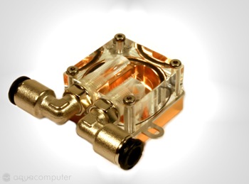
Cuplex evo 1.1
I just loved the design of this waterblock and as my motherboard doesn't have mounting holes I was limited to what I could use fortuantly these guys enable you to choose what mounting bracket you require for your motherboard - more shiney toys!
Twinplex Rev. 1.2
Next was the Graphic card block which can be mounted on the chipset as well although they make around 8 different specs of the same block depending on where and how you wich to attach it. (Also they all come in Sterling Silver as well!)
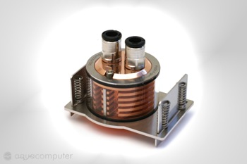
Aquatube Rev. 1.1
Now this resivour plays a very important role to my case mod which is actually the 1st thing that caught my eye and got the projecting moving. It comes with a mounting bracket to either mount in 2 drive bays or externally - I decided to go external!
As you can see these are images taken from the website once I either get some hosting or my FTP serverback up I will post actual shots of this kit.
Cuplex evo 1.1
I just loved the design of this waterblock and as my motherboard doesn't have mounting holes I was limited to what I could use fortuantly these guys enable you to choose what mounting bracket you require for your motherboard - more shiney toys!
Twinplex Rev. 1.2
Next was the Graphic card block which can be mounted on the chipset as well although they make around 8 different specs of the same block depending on where and how you wich to attach it. (Also they all come in Sterling Silver as well!)
Aquatube Rev. 1.1
Now this resivour plays a very important role to my case mod which is actually the 1st thing that caught my eye and got the projecting moving. It comes with a mounting bracket to either mount in 2 drive bays or externally - I decided to go external!
As you can see these are images taken from the website once I either get some hosting or my FTP serverback up I will post actual shots of this kit.
As you can see the lapjob is excellent! I was very impressed also at the measures they took to protect it via shipping.

And this is it connected with the socket clips

I really am impressed with the quality of this equipment, everything has a wow factor as I'm totaly new to watercooling! :p
Those marks you can see are my grubby finger prints!
And this is it connected with the socket clips
I really am impressed with the quality of this equipment, everything has a wow factor as I'm totaly new to watercooling! :p
Those marks you can see are my grubby finger prints!
I wanted to fit both the reservoir and the radiator on the top of the case as the reservoir has a nice mounting bracket and window that I mentioned above. Also the workmanship of these is excellent and the fixing bolts really add to the feel of the case. Originally I wanted a twin fan radiator but due to the dimensions of this case it proved impossible to have the PSU, Radiator and reservoir mounted on the top of the case (case dimensions L540 x W198 x H458 mm) so I decided to go for the single mount radiator as this would allow me to fit everything in…… Even if it was a very tight fit!
I had to totally dismantle this case in order to work with it and I found out one of the major flaws in this case, everything is mounted with rivets! Now for a case of this price that is really bad $191.00 US or $139.99 US special offer and I know for the same price you can get a full tower with all the little things we moders expect……. But I suppose you pay for the looks. Any way not to worry I just need to break out my friend!

I spent a lot of time marking and remarking and getting everything perfect because as I said due to the dimensions every millimeter mattered! I used a thick tape to cover the area I was working on and used several layers as I didn’t want to slip and ruin the finish of this case so I took my time and got it all laid out correctly….. Law #1 Take you Time and check, check and check again!

As you can see I marked everything out including where the actual reservoir would sit. The angle is a little funny in this photo as it’s balancing on my chair and the lens is a wide angle zoom lens so it makes things looked a little curved.
I then stamped the holes to make a pilot hole ready for drilling as if I drilled after I cut out the areas for the reservoir and radiator It would weaken the metal and maybe cause buckling on the mounting areas….. So drill 1st then cut!

Fixing holes drilled areas cut and not a slip in site! Grrr as you can see the mounting bracket for the PSU cuts straight across where my radiator is going to sit, well seen as I had my Black and Decker out! Also by removing the top bar it wouldn't weaken the support as it's still supported at the sides (Not shown)

Nice and clean although the angle was very hard to work at due to the irremovable drive cage! (Maybe that’s going to get moded to! We will have to see! Spot the broken cutting disk!)
My local DIY store had these great cutting disks that are twice the size of standard Rotary / Dremel cutting disks and I found that they didn’t shatter and lasted funnily enough twice as long! Also it enabled me to cut the lines straighter, which is a blessing as it means less work with the sander.
Oh and by the way…… always use Eye protection and a filter mask…. God knows how bad that powder is for you and I had black bogies for two days after that cutting!
I had to totally dismantle this case in order to work with it and I found out one of the major flaws in this case, everything is mounted with rivets! Now for a case of this price that is really bad $191.00 US or $139.99 US special offer and I know for the same price you can get a full tower with all the little things we moders expect……. But I suppose you pay for the looks. Any way not to worry I just need to break out my friend!
I spent a lot of time marking and remarking and getting everything perfect because as I said due to the dimensions every millimeter mattered! I used a thick tape to cover the area I was working on and used several layers as I didn’t want to slip and ruin the finish of this case so I took my time and got it all laid out correctly….. Law #1 Take you Time and check, check and check again!
As you can see I marked everything out including where the actual reservoir would sit. The angle is a little funny in this photo as it’s balancing on my chair and the lens is a wide angle zoom lens so it makes things looked a little curved.
I then stamped the holes to make a pilot hole ready for drilling as if I drilled after I cut out the areas for the reservoir and radiator It would weaken the metal and maybe cause buckling on the mounting areas….. So drill 1st then cut!
Fixing holes drilled areas cut and not a slip in site! Grrr as you can see the mounting bracket for the PSU cuts straight across where my radiator is going to sit, well seen as I had my Black and Decker out! Also by removing the top bar it wouldn't weaken the support as it's still supported at the sides (Not shown)
Nice and clean although the angle was very hard to work at due to the irremovable drive cage! (Maybe that’s going to get moded to! We will have to see! Spot the broken cutting disk!)
My local DIY store had these great cutting disks that are twice the size of standard Rotary / Dremel cutting disks and I found that they didn’t shatter and lasted funnily enough twice as long! Also it enabled me to cut the lines straighter, which is a blessing as it means less work with the sander.
Oh and by the way…… always use Eye protection and a filter mask…. God knows how bad that powder is for you and I had black bogies for two days after that cutting!
Now the holes are cutting and the mounting areas drilled out it’s time to see if the mounting brackets and grills fit, As I keep saying the guys at aqua-computer have really gone out of their way to design a aesthetically pleasing product as possible while also catering for us overclockers.

Everything fits perfectly! One of the worrying stages is out of the way cleanly cut case with no mess ups. The photo was taken without the flash on so it all looks a bit dull. Later I will post shiney pictures! Some of you might be saying that Doesn’t putting your reservoir there mean you lose 2 drive bays? Well in fact I will only lose one as I will be putting something in the 2nd drive bay that won’t interfere with the reservoir.
One of the great things about the pump I used is that it’s a modified Ehiem 1046 and connects to either a Molex or the aqua-stream controller.
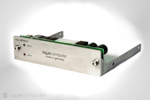
The pump controller mounts in the floppy drive bay, now I thought this came separately from the pump and I didn’t take it into account when I purchased the pump or when I was designing where everything would go. So you can understand my surprise upon opening the box and finding something I didn’t expect to get and also the dilemma I was in as I now head no idea where I was going to put it as I didn’t want to lose anymore bays to hardware. As I needed that floppy bay for my floppy drive card reader combo.

I love this thing and If you like me and do a lot of digital photography they come in real handy.
Now having had lunch a coke I was ready to come back and tackle this problem I have this pump controller, it looks damn cool and I have it so I’m going to use it! So looking back over my case I realized that I had just the perfect amount of space in between the reservoir and the radiator grill, So I take everything out (of course after several minutes of puffing my chest out at the work done so far and getting all excited like a 5 year old on Christmas morning!) Taped up and got ready to cut the hole for the pump controller…..
[Insert squealing break sound effect here]
I almost ruined everything! I realized when looking at the pump controller that cutting a hole and mounting wouldn’t work as the circuit board is exactly the same length as the cover plate and I wouldn’t be able to mount it to anything. After another coke (Coke is your modding friend!) I realized that I only had to drill four very small holes 2 for the mounting bolts and two for the LEDS Also I would need to shorten the mounting bolts by 3mm to make up for loss of the bay mounting bracket and also the thickness of the case to allow the LEDS to reach the face plate.

That bendy camera is back!As you can see it all works very well together and i just love those mounting bolts! So now it was time to insert all the hardware, reservoir, radiator, PSU and now the newly added Pump controller! Does it all fit?
Everything fits perfectly! One of the worrying stages is out of the way cleanly cut case with no mess ups. The photo was taken without the flash on so it all looks a bit dull. Later I will post shiney pictures!
Some of you might be saying that Doesn’t putting your reservoir there mean you lose 2 drive bays? Well in fact I will only lose one as I will be putting something in the 2nd drive bay that won’t interfere with the reservoir.One of the great things about the pump I used is that it’s a modified Ehiem 1046 and connects to either a Molex or the aqua-stream controller.
The pump controller mounts in the floppy drive bay, now I thought this came separately from the pump and I didn’t take it into account when I purchased the pump or when I was designing where everything would go. So you can understand my surprise upon opening the box and finding something I didn’t expect to get and also the dilemma I was in as I now head no idea where I was going to put it as I didn’t want to lose anymore bays to hardware. As I needed that floppy bay for my floppy drive card reader combo.
I love this thing and If you like me and do a lot of digital photography they come in real handy.
Now having had lunch a coke I was ready to come back and tackle this problem I have this pump controller, it looks damn cool and I have it so I’m going to use it! So looking back over my case I realized that I had just the perfect amount of space in between the reservoir and the radiator grill, So I take everything out (of course after several minutes of puffing my chest out at the work done so far and getting all excited like a 5 year old on Christmas morning!) Taped up and got ready to cut the hole for the pump controller…..
[Insert squealing break sound effect here]
I almost ruined everything! I realized when looking at the pump controller that cutting a hole and mounting wouldn’t work as the circuit board is exactly the same length as the cover plate and I wouldn’t be able to mount it to anything. After another coke (Coke is your modding friend!) I realized that I only had to drill four very small holes 2 for the mounting bolts and two for the LEDS Also I would need to shorten the mounting bolts by 3mm to make up for loss of the bay mounting bracket and also the thickness of the case to allow the LEDS to reach the face plate.
That bendy camera is back!As you can see it all works very well together and i just love those mounting bolts! So now it was time to insert all the hardware, reservoir, radiator, PSU and now the newly added Pump controller! Does it all fit?
Trying to install all the hardware was a little tricky as I had to install the Radiator 1st followed by the reservoir and then lastly I had to work in the amazingly cramped space between the reservoir and the radiator to fit the pump controller! Remeber none of the cages are removable due to them being rivited in place..... I will get round to modding that!

As you can see it all fits but only just ……as I said before every millimeter counted on this case mod! Oh i forgot to say theres a 120mm Fan sandwiched between the radiator and the case!
Oh so fiddly !
Looking side on (Bendy camera either that or that 120mm fan is more powerful than I thought!) you can see that I only have a 2cm gap between the PSU and the radiator but it’s perfect for the cables and it will look better once I have sleeved it and tidied it away.

Looking front on into the case, as you can see the reservoir takes one bay and the tube connectors eat into the second bay but not to worry I have something super yummy to utilize the area and prevent the loss of space! But more about that later!
Your probably thinking what the hell is that wire doing coming out of the reservoir? Well one of the nice little things about the reservoir is that it has 6 barbs? (Tube mounting) options to cater for all mounting requirements. On top of that they do a clear plug, which is bored out so you can fit a LED of your choice, in this case Blue to match that of the LEDS that come with the case.
Uh-oh..... I feel Down Town Tokyo mods are crawling into my plans!

As you can see it all fits but only just ……as I said before every millimeter counted on this case mod! Oh i forgot to say theres a 120mm Fan sandwiched between the radiator and the case!
Oh so fiddly !
Looking side on (Bendy camera either that or that 120mm fan is more powerful than I thought!) you can see that I only have a 2cm gap between the PSU and the radiator but it’s perfect for the cables and it will look better once I have sleeved it and tidied it away.
Looking front on into the case, as you can see the reservoir takes one bay and the tube connectors eat into the second bay but not to worry I have something super yummy to utilize the area and prevent the loss of space! But more about that later!
Your probably thinking what the hell is that wire doing coming out of the reservoir? Well one of the nice little things about the reservoir is that it has 6 barbs? (Tube mounting) options to cater for all mounting requirements. On top of that they do a clear plug, which is bored out so you can fit a LED of your choice, in this case Blue to match that of the LEDS that come with the case.
Uh-oh..... I feel Down Town Tokyo mods are crawling into my plans!
Ok, well the next step was to mount the pump as I had installed the pump monitor on the top of the case I needed to place it near to it to reduce the cable clutter. I originally wanted to put it in the HDD bay at the bottom but was worried that it would interfere with the 3 drives I had in there and I really didn't want to change the original plan of two drives in Raid 0 and 1 standard back up. To go along with the DVD burner and the DVD drive.
After playing around I realized the only way to do this is with L-bend barbs on the pump. So again I caught the train to Akihabara and bought some more! They are beginning to think I want to work there!
After working out how far back to place the pump I decided to place it so it couldn't be seen, this meant removing the totally ineffective fan cage mounted in the HDD bay. Again using rivets so out with the Black and Decker to remove those annoying rivets!
Well due to the irremovable drive bay (Did I mention I should modify that?) It was very hard to drill the holes. I prefer to work on the side that won't be seen even though the underside won't be seen I still consider it a visible area don't know why. But in this instance I had to flip her on her back and mark out the mounting holes and drill, I was a little worried as I wasn't sure if those rivets could withstand the force of the drill coming through on them but the seem to have held firm.
As you can see by the two photos there really isn't a lot of space between the outlet on the pump and the 1st HDD.

As you can see I have lost 2 of the HDD slots leaving me only 3 to put drives in! Thank God thats all I need!

You might be wondering what that T-section is? Well after numerous setups and leak testing I decided that one of these would be extremely useful needless to say it prevents a lot of mess.

After all the hardware was in place the next step was to cut the tubing, as most of you would agree it's probably one of the most time consuming things. Cut the tubing, get everything in place, fill it with water, find out the bend is too tight and it leaks, empty the water, cut more tubing fill it with water and so on.
One of the tricks I did learn was that if you are using hard tubing warm it up in hot water, around 40-50c is good as this will allow the tubing to bend and be more pliable and once the cold water runs through it hardens back up and doesn't leak while retaining the bend you put in it.
I first mounted the water block on the GPU and had real problems getting all the tubing set up as I had a split so that the CPU and GPU weren't in series but used separate lines but it kept leaking (This is how I found up the heating trick!) and had to return to the store twice to buy L-bend barbs, the store is 1 and a half hours away by train so I was getting quiet tired that day.

I finally got it all set up and in place, by the way the GPU water block has the same excellent lapping as the CPU water block. Did I mention you can get them in sterling silver?
But I kept on getting leaks and couldn't work out where or why!
After playing around I realized the only way to do this is with L-bend barbs on the pump. So again I caught the train to Akihabara and bought some more! They are beginning to think I want to work there!
After working out how far back to place the pump I decided to place it so it couldn't be seen, this meant removing the totally ineffective fan cage mounted in the HDD bay. Again using rivets so out with the Black and Decker to remove those annoying rivets!
Well due to the irremovable drive bay (Did I mention I should modify that?) It was very hard to drill the holes. I prefer to work on the side that won't be seen even though the underside won't be seen I still consider it a visible area don't know why. But in this instance I had to flip her on her back and mark out the mounting holes and drill, I was a little worried as I wasn't sure if those rivets could withstand the force of the drill coming through on them but the seem to have held firm.
As you can see by the two photos there really isn't a lot of space between the outlet on the pump and the 1st HDD.
As you can see I have lost 2 of the HDD slots leaving me only 3 to put drives in! Thank God thats all I need!
You might be wondering what that T-section is? Well after numerous setups and leak testing I decided that one of these would be extremely useful needless to say it prevents a lot of mess.
After all the hardware was in place the next step was to cut the tubing, as most of you would agree it's probably one of the most time consuming things. Cut the tubing, get everything in place, fill it with water, find out the bend is too tight and it leaks, empty the water, cut more tubing fill it with water and so on.
One of the tricks I did learn was that if you are using hard tubing warm it up in hot water, around 40-50c is good as this will allow the tubing to bend and be more pliable and once the cold water runs through it hardens back up and doesn't leak while retaining the bend you put in it.
I first mounted the water block on the GPU and had real problems getting all the tubing set up as I had a split so that the CPU and GPU weren't in series but used separate lines but it kept leaking (This is how I found up the heating trick!) and had to return to the store twice to buy L-bend barbs, the store is 1 and a half hours away by train so I was getting quiet tired that day.
I finally got it all set up and in place, by the way the GPU water block has the same excellent lapping as the CPU water block. Did I mention you can get them in sterling silver?
But I kept on getting leaks and couldn't work out where or why!
Well I found out where the leak was coming from! I had a faulty radiator! One of the barbs had a crack in it and it would only leak ones all the air was out of the system and was running at full pressure! I’m so glad I leak tested for 24 hours without any equipment inside! So recommendation for any new comers to water cooling like myself….. Leak test without any of your hardware in place, Motherboard included! I gave the stockist a quick call and they said they would be happy to change it, so back on the train and 3 hours later I was home with the new radiator. I decided that as I was tired out I would leave it for the day and install it on the Sunday…. 30 minutes later I installed it and had it ready for another 24 hour leak testing! (Hey why waste time!)
Next morning got up and was very happy to see there were no puddles in the bottom of the case, so I decided it was time to take a deep breath and insert the Motherboard and Graphics card and test for another 12 hours. As you can see with the pump and reservoir out of view it gives the viewable area a cleaner look which is what I want for when I cut the window.

Next was to fill it with water and to see if every thing loaded up correctly and hadn’t died. I was a little worried about the ATI Radeon 9800 Pro as when I first mounted the waterblock I slightly crushed the core on the bottom right corner (Sorry no Picture) and I was eager to see if it all loaded up. Fortunately everything booted up fine and I was able to run 3DMark03 for 6 hours on loop just to be sure.

As you can see with the same overclock that I had on air I’m 43c and that’s without water wetter and the fan turning over idly.
This is looking down on the reservoir 1st is without the light and the 2nd is with. Ohhhhhh so pretty.

This next image also has the sealing cap over the top and the water level higher ...Once it's all setup the reservoir will be filled to the same height as in the 1st picture as i like that effect.

Next morning got up and was very happy to see there were no puddles in the bottom of the case, so I decided it was time to take a deep breath and insert the Motherboard and Graphics card and test for another 12 hours. As you can see with the pump and reservoir out of view it gives the viewable area a cleaner look which is what I want for when I cut the window.
Next was to fill it with water and to see if every thing loaded up correctly and hadn’t died. I was a little worried about the ATI Radeon 9800 Pro as when I first mounted the waterblock I slightly crushed the core on the bottom right corner (Sorry no Picture) and I was eager to see if it all loaded up. Fortunately everything booted up fine and I was able to run 3DMark03 for 6 hours on loop just to be sure.
As you can see with the same overclock that I had on air I’m 43c and that’s without water wetter and the fan turning over idly.
This is looking down on the reservoir 1st is without the light and the 2nd is with. Ohhhhhh so pretty.
This next image also has the sealing cap over the top and the water level higher ...Once it's all setup the reservoir will be filled to the same height as in the 1st picture as i like that effect.
While I had the system up and running I notice that the HDD’s where poking out over the motherboard and the cabling causing a lot of clutter! I can’t be having that!
You can see by these photo’s the amount of space wasted especially with that Stupid fan cage removed a whole 3.5 cm wasted! It would be fine if the airflow from the front of the case was good but as everyone knows its poo!


So it’s out with the ruler and drills again! To reclaim that 3.5 cm that belongs to me!
I didn’t want to remove the pump or drain the system again just yet so I rigged up the vacuum cleaner to pull all the shrapnel away as I was drilling …wife likes this too as it keeps her house clean and tidy!
Any way I drilled the pilot holes and then used the Black & Decker to join the dots kind of a hash job as you can see from the photo’s but it works and once the side panel is back on you won’t see it.

And as you can see I have reclaimed those precious 3.5cm!


Fortunately the 3rd HDD will be going in the drive bays above…. Why these have the elongated holes and the others don’t I have no idea but at least I won’t have to modify the case for a while.
You can see by these photo’s the amount of space wasted especially with that Stupid fan cage removed a whole 3.5 cm wasted! It would be fine if the airflow from the front of the case was good but as everyone knows its poo!
So it’s out with the ruler and drills again! To reclaim that 3.5 cm that belongs to me!
I didn’t want to remove the pump or drain the system again just yet so I rigged up the vacuum cleaner to pull all the shrapnel away as I was drilling …wife likes this too as it keeps her house clean and tidy!
Any way I drilled the pilot holes and then used the Black & Decker to join the dots kind of a hash job as you can see from the photo’s but it works and once the side panel is back on you won’t see it.
And as you can see I have reclaimed those precious 3.5cm!
Fortunately the 3rd HDD will be going in the drive bays above…. Why these have the elongated holes and the others don’t I have no idea but at least I won’t have to modify the case for a while.
I decided that after all the work cutting and moding the case I wanted to do something a little laid back and fun. (Not saying that what I have done previously wasn’t fun)
So I decided to work on the look of the front of the case. I already had the design in mind and it revolves around the bolts on the top of the case. I love the brushed Aluminum look but also wanted something more to emphasise the style of the case.
So using the standard face plate I started on the next stage.

What I intended to do was to totally be done with the plastic face plates on the optical drives and cut my own using the bezels, Now as you are aware you only have a limited number of these to work with so I was worried about making mistakes, in this instance 2 tries per drive. So I worked everything out measured, re-measured made a mockup and marked it out on the piece to be cut. After around 2 hours of work I came out with this!

Now I’m extremely pleased with this piece of work and in this shot I hadn't even sanded and buffed the edges, but unfortunately God wasn’t impressed at all, in fact he had other plans for my case. Around 20 minutes after completing the face plate Yokohama was hit by a mild 3.2 earthquake, nothing serious just a nice little rocking motion, nothing serious enough to cause any damage, but enough to knock things over …. Like DVD drives sat up right on my desk and look what happened, as you can guess I was extremely annoyed to say the least!

So with the defacing of the Sony’s DVD read-writer I was stumped, I had spent all this time making that face plate only to have the tray face plate smashed! Time to hit the forums and see what other people are doing!
Having spent an hour looking around the forums I came across this thread by RangerJoe and was really impressed with his finished look, I hadn’t even thought about stealthing my drives but if I had seen that thread I think I would have gone stealth from the start!
So what follows is a walk through on how to stealth your drives with also the added benefit of being able to open them without having to “Eject from Desktop”.
So I decided to work on the look of the front of the case. I already had the design in mind and it revolves around the bolts on the top of the case. I love the brushed Aluminum look but also wanted something more to emphasise the style of the case.
So using the standard face plate I started on the next stage.
What I intended to do was to totally be done with the plastic face plates on the optical drives and cut my own using the bezels, Now as you are aware you only have a limited number of these to work with so I was worried about making mistakes, in this instance 2 tries per drive. So I worked everything out measured, re-measured made a mockup and marked it out on the piece to be cut. After around 2 hours of work I came out with this!
Now I’m extremely pleased with this piece of work and in this shot I hadn't even sanded and buffed the edges, but unfortunately God wasn’t impressed at all, in fact he had other plans for my case. Around 20 minutes after completing the face plate Yokohama was hit by a mild 3.2 earthquake, nothing serious just a nice little rocking motion, nothing serious enough to cause any damage, but enough to knock things over …. Like DVD drives sat up right on my desk and look what happened, as you can guess I was extremely annoyed to say the least!
So with the defacing of the Sony’s DVD read-writer I was stumped, I had spent all this time making that face plate only to have the tray face plate smashed! Time to hit the forums and see what other people are doing!
Having spent an hour looking around the forums I came across this thread by RangerJoe and was really impressed with his finished look, I hadn’t even thought about stealthing my drives but if I had seen that thread I think I would have gone stealth from the start!
So what follows is a walk through on how to stealth your drives with also the added benefit of being able to open them without having to “Eject from Desktop”.
[Size=4]Optical Drive Stealthing [/size]
So taking the original face plate that came with the case I started on the path of stealth. Now I now a lot of you know how to do this but while searching the forums I couldn’t really find a post walking people through this mod, so I thought I would do so from beginning to end.
Objectives
To make optical drives invisible to the eye.
Enable the drives to be opened without using “Eject from Desktop”
To have a stylish finish that is in keeping with the style of the case.
Method
Ok the 1st step is to remove the tabs on your case bezel. I used the Black and Decker rotary tool for this. As you can see from the 1st photo my bezel has an edge to it which I wanted to keep.
The mounting tabs have been removed and sanded down to remove any sharp edges.

This step I did was to add a plexi-glass cover for the drive as I wanted to add to the feel of the case, this is totally optional and is more about aesthetics than stealthing at this point.
The next step was to drill the mounting holes into the face plate, after working out the best position I used a punch mark to guide the drill. Remember that you only want to make a slight indentation so just hit it lightly, hitting it to hard could put the punch marker through you face plate and warp it.

The next step was to drill the holes for the bolts. I put the drill on a slower speed as I didn’t want it slipping and ruining the finish of the face plate. And the only force necessary was the actual weight of the drill.

As you can see from the above Photo the holes are very neat and tidy, I flipped it over and using a small file I removed the debris from around the holes.
The next shot is of all the equipment I used for cutting the plexi,

This shot shows a cutting tool designed for what we are doing, I don’t like to use a rotary cutting tool as they tend to melt the plastic and can warp the piece you are cutting, this tool in conjunction with a metal rule causes a series of deep scratches which enable you to snap a perfectly straight clean line along the area you are working on.

So taking the original face plate that came with the case I started on the path of stealth. Now I now a lot of you know how to do this but while searching the forums I couldn’t really find a post walking people through this mod, so I thought I would do so from beginning to end.
Objectives
To make optical drives invisible to the eye.
Enable the drives to be opened without using “Eject from Desktop”
To have a stylish finish that is in keeping with the style of the case.
Method
Ok the 1st step is to remove the tabs on your case bezel. I used the Black and Decker rotary tool for this. As you can see from the 1st photo my bezel has an edge to it which I wanted to keep.
The mounting tabs have been removed and sanded down to remove any sharp edges.
This step I did was to add a plexi-glass cover for the drive as I wanted to add to the feel of the case, this is totally optional and is more about aesthetics than stealthing at this point.
The next step was to drill the mounting holes into the face plate, after working out the best position I used a punch mark to guide the drill. Remember that you only want to make a slight indentation so just hit it lightly, hitting it to hard could put the punch marker through you face plate and warp it.
The next step was to drill the holes for the bolts. I put the drill on a slower speed as I didn’t want it slipping and ruining the finish of the face plate. And the only force necessary was the actual weight of the drill.
As you can see from the above Photo the holes are very neat and tidy, I flipped it over and using a small file I removed the debris from around the holes.
The next shot is of all the equipment I used for cutting the plexi,
This shot shows a cutting tool designed for what we are doing, I don’t like to use a rotary cutting tool as they tend to melt the plastic and can warp the piece you are cutting, this tool in conjunction with a metal rule causes a series of deep scratches which enable you to snap a perfectly straight clean line along the area you are working on.
I used the face plate to mark out the area I will be cutting including the holes for the mounting bolts, now one thing I have learnt is that plexi loves to shatter or snap when drilled so I decided to drill out the holes 1st then cut it. I used the drill on the lowest setting and again used only the weight of the drill as pressure, go slowly.

Then using the cutting tool and ruler I scored deep lines across the marked lines, now be really careful and use a metal rule as this cutter will eat plastic one alive, as well as any body parts that get in the way.

This bled for ages and left me slightly handicapped for this job…. Try doing something without using your thumbs!
As you can see the scorer/cutter leaves a very clean finish that requires only a small amount of filing. Those deep scratches you can see are actually on the cutting board beneath the face plate….. I got in to trouble for that from the wife so make sure you work on something that is suitable… your dinning room table is a big no no!

After this I rounded off the corners to give a more stylized finish to the face plate and also to remove any sharp edges that I might catch myself on while inserting disks. The next shot shows the finished pieces awaiting assembly

The bolts I used are screwed in using an Alan key which match the fittings on the water cooling hardware so again it’s adding to the theme of the case.

As you can see when flipped over the bolts will interfere with the closing CD-tray so using a small cutting disk I removed the access length and sanded it to remove sharp edges.
Now we have the face plate finished we can actually stealthing that drive!
The first thing I did was to cut a piece of plexi a little bit small than the drive tray face plate that was also the same thickness as the case bezel (I used two layers of plexi to achieve this).
Note: Some face plates are an odd shape, take a look in my previous post at the Sony’s face plate, you might need to remove yours like I did and work directly on the CD-tray.
Then using the cutting tool and ruler I scored deep lines across the marked lines, now be really careful and use a metal rule as this cutter will eat plastic one alive, as well as any body parts that get in the way.
This bled for ages and left me slightly handicapped for this job…. Try doing something without using your thumbs!
As you can see the scorer/cutter leaves a very clean finish that requires only a small amount of filing. Those deep scratches you can see are actually on the cutting board beneath the face plate….. I got in to trouble for that from the wife so make sure you work on something that is suitable… your dinning room table is a big no no!
After this I rounded off the corners to give a more stylized finish to the face plate and also to remove any sharp edges that I might catch myself on while inserting disks. The next shot shows the finished pieces awaiting assembly
The bolts I used are screwed in using an Alan key which match the fittings on the water cooling hardware so again it’s adding to the theme of the case.
As you can see when flipped over the bolts will interfere with the closing CD-tray so using a small cutting disk I removed the access length and sanded it to remove sharp edges.
Now we have the face plate finished we can actually stealthing that drive!
The first thing I did was to cut a piece of plexi a little bit small than the drive tray face plate that was also the same thickness as the case bezel (I used two layers of plexi to achieve this).
Note: Some face plates are an odd shape, take a look in my previous post at the Sony’s face plate, you might need to remove yours like I did and work directly on the CD-tray.
Next I used an industrial strength double sided tape, to tape the piece of plexi to the drive tray and then another piece of tape to stick to the Case bezel. Now here’s a little trick for you to align the bezel and the tray perfectly.

Plug you drive back in and close the CD-tray remove the protective film from the tape and align the case bezel over the top of the drive.
Eject your CD-tray using “Eject from desktop” and hold the Case bezel firmly over the CD-tray. The tray should then affix itself to the back of the case bezel.
Let go of the bezel and then re-eject the CD-tray and while holding the CD-tray firmly push the case bezel to get a good bond. This is the CD-Drive plate attached to the case bezel.

The next step is to rig a way of opening the drive without using the “Eject from Desktop” method.
I did exactly the same to the button as I did the CD-tray face plate but instead of making it a little small I made it a bit bigger, again the same thickness as the case bezel but remember it only needs to be slightly touching the “eject button” as the slightest bit of pressure will goes the tray to keep opening.
This time I attached a very small piece of double-sided tape to the eject button to hold the plexi in place then and a large piece on top to connect to the case bezel. Then taping the eject button I closed the case.
Then pushing down firmly on the area where the plexi glass touches the eject button I opened the CD-tray, now with a bit of luck you r small piece of tape won’t be able to hold back the CD-tray and pull free of the eject button. Like this:

I then removed the small piece so that it couldn’t stick to the button again and tried the action a few times to make sure it was all aligned and working, especially the eject button.
Conclusion
As you can see I think the stealth mod was a way better idea than my original plans!


[Size=3]A big thanks goes out to RangerJoe for the inspiration of this mod and also his excellent stealthing skills![/size]
Plug you drive back in and close the CD-tray remove the protective film from the tape and align the case bezel over the top of the drive.
Eject your CD-tray using “Eject from desktop” and hold the Case bezel firmly over the CD-tray. The tray should then affix itself to the back of the case bezel.
Let go of the bezel and then re-eject the CD-tray and while holding the CD-tray firmly push the case bezel to get a good bond. This is the CD-Drive plate attached to the case bezel.
The next step is to rig a way of opening the drive without using the “Eject from Desktop” method.
I did exactly the same to the button as I did the CD-tray face plate but instead of making it a little small I made it a bit bigger, again the same thickness as the case bezel but remember it only needs to be slightly touching the “eject button” as the slightest bit of pressure will goes the tray to keep opening.
This time I attached a very small piece of double-sided tape to the eject button to hold the plexi in place then and a large piece on top to connect to the case bezel. Then taping the eject button I closed the case.
Then pushing down firmly on the area where the plexi glass touches the eject button I opened the CD-tray, now with a bit of luck you r small piece of tape won’t be able to hold back the CD-tray and pull free of the eject button. Like this:
I then removed the small piece so that it couldn’t stick to the button again and tried the action a few times to make sure it was all aligned and working, especially the eject button.
Conclusion
As you can see I think the stealth mod was a way better idea than my original plans!
[Size=3]A big thanks goes out to RangerJoe for the inspiration of this mod and also his excellent stealthing skills![/size]
Extra
Some of you might have noticed a mark in the bottom right hand corner of the stealthed drive, well this is a little extra I add, technically I have de-stealthed it and I’m not sure if it’s going to stay yet so let me know what you think.
While at the huge electronics store near where I live I came across these clear sticker sheets that can be printed on using an Inkjet printer. So I bought a sheet and decided to add some decals to the stealthed drives just to remind people where to push when using my PC.
I got the font selection down to two types I liked and printed them off.

In the end I decided only to put the “push” decal as I thought the others would really ruin the effect.

Let me know what you think comments are always welcome and only help me improve on what I have done. Also now the glue on the back of the decal has set it's very hard to see the outline and even harder once it's installed.
Some of you might have noticed a mark in the bottom right hand corner of the stealthed drive, well this is a little extra I add, technically I have de-stealthed it and I’m not sure if it’s going to stay yet so let me know what you think.
While at the huge electronics store near where I live I came across these clear sticker sheets that can be printed on using an Inkjet printer. So I bought a sheet and decided to add some decals to the stealthed drives just to remind people where to push when using my PC.
I got the font selection down to two types I liked and printed them off.
In the end I decided only to put the “push” decal as I thought the others would really ruin the effect.
Let me know what you think comments are always welcome and only help me improve on what I have done. Also now the glue on the back of the decal has set it's very hard to see the outline and even harder once it's installed.
SoundBlaster Audigy Mod
Some of you out there might have the same Sound card as me, the SoundBlaster Audigy Platinum EX.
Now this card although not the best is still pretty good and I like the external port that I can sits on my desk.

Although I do have one major gripe about it and that’s the HUGE IDE cable connecting the main Audigy card to the external connection port. I mean this thing is not only long but it’s damn wide as well!

Now in my old case that wasn’t such a problem as I had the space, although the cable did catch a lot of dust! But in this case I don’t want ugly ribbon cables hanging out and catching dust, so I went about making my own rounded cables for it.
Firstly I cut the ribbon into 3 strand sections using a sharp knife. You don’t need to cut the whole length just about 2-3cm and then you can gently tease them apart. I cut all the sections first then eased them apart one by one.

The next step was to twist them into rounded cables and secure them with zip-ties, they are starting to look more appealing now! I’m not sure of the technical side and if twisting them will cause problems if so I will get those Isolators (Magnets) that clip to either end of the cable.

Next step was to wrap them, Now I first thought of using heat shrink to do this and If you look at the following photo one of them is done with ordinary isolation tape and the other is done with heat shrink and to be honest, even looking at it now It’s hard to tell which one is tape and which one is heat shrink.

As you can see the finished product is very clean and clutter free, the original length of cable was around 50cm and had to be folded numerous times just to keep it tidy and out of the way.

I’m thinking of re-doing this and using a silver type of tape as this will match the rounded IDE cables I’m using for the optical drives and the one ATA drive, I would love to get hold of some silver SATA cables but all I can find is Red or Blue ones.
Some of you out there might have the same Sound card as me, the SoundBlaster Audigy Platinum EX.
Now this card although not the best is still pretty good and I like the external port that I can sits on my desk.
Although I do have one major gripe about it and that’s the HUGE IDE cable connecting the main Audigy card to the external connection port. I mean this thing is not only long but it’s damn wide as well!
Now in my old case that wasn’t such a problem as I had the space, although the cable did catch a lot of dust! But in this case I don’t want ugly ribbon cables hanging out and catching dust, so I went about making my own rounded cables for it.
Firstly I cut the ribbon into 3 strand sections using a sharp knife. You don’t need to cut the whole length just about 2-3cm and then you can gently tease them apart. I cut all the sections first then eased them apart one by one.
The next step was to twist them into rounded cables and secure them with zip-ties, they are starting to look more appealing now! I’m not sure of the technical side and if twisting them will cause problems if so I will get those Isolators (Magnets) that clip to either end of the cable.
Next step was to wrap them, Now I first thought of using heat shrink to do this and If you look at the following photo one of them is done with ordinary isolation tape and the other is done with heat shrink and to be honest, even looking at it now It’s hard to tell which one is tape and which one is heat shrink.
As you can see the finished product is very clean and clutter free, the original length of cable was around 50cm and had to be folded numerous times just to keep it tidy and out of the way.
I’m thinking of re-doing this and using a silver type of tape as this will match the rounded IDE cables I’m using for the optical drives and the one ATA drive, I would love to get hold of some silver SATA cables but all I can find is Red or Blue ones.
Total Power Supply Modification Part 1
Maybe some of you like me are a little annoyed with the state of their cabling inside their system, especially if they have a window or require a good airflow through the case. Now a lot of out the box PSU’s tend in my opinion to be cluttered with lots of excessive cables and Molex attachments so my plan was to rebuild my PSU to my cases specifications but with the added bonus of being able to adapt it to any case or configuration if necessary.
[Size=3]WARNING MODIFIYING YOUR PSU CAN BE DANGEROUS AND COULD RESULT IN EITHER DAMAGE TO YOUR HARDWARE OR INJURY OR DEATH [/size]

Objective
To modify the PSU to reduce clutter.
To have a product than can adapt to any case configuration.
To reduce the visual impact of cabling inside the case.
To have a professional looking finished product.
Method
As you can see my standard PSU is an octopus of wiring and cables when installed it is also an eyesore and almost impossible to hide in the case. It also has a few cable types that are no longer used and where taped up and hidden in my last case. Due to the size limitations of the new case and also the amount of hardware crammed in there the amount of hiding space has been reduced quite a lot.

The 1st thing I did was to remove the surplus and obsolete cables. I opened the PSU and removed them from the source as I didn’t want any loose cables floating around and I would be rather safe than sorry. Again take care when working inside your PSU, Mine hasn’t been used in a week so I felt slightly reassured that there was very little or no charge left in it but I was extremely careful not to touch anything as I wasn’t sure.


The next step was to remove those Gold fan guards as I felt they no longer added to the feel to the case and the plain silver ones would do until the custom ones were ready. I also gave it a good clean out with a duster and the vacuum cleaner as the amount of dust in there was amazing. I also wanted to swap over the stock fans for some cooler master fans with LED’s but they didn’t fit so I might go out looking for slim fans with LED’s or convert the ones I have using the ones off the cooler master fans.

Once it was all back together it was time to work on sorting out that mess of cables! Out with the wire snips. What I did was measure the distance from the PSU to the best hiding place in my case to start my wiring from, on this case the best place is behind the motherboard tray as I have around 2cm depth between the back of the motherboard tray and the case side panel. So I cut the wires back but left an extra 4cm just incase of accidents while doing the modification. Then I had to remove the pins from the Molex and re-solder them back on to the wires and re-connect the Molex socket. This is very fiddly and you have to be careful not to break the latches when removing… I used a very small flat head screw driver for watches to do this.

Maybe some of you like me are a little annoyed with the state of their cabling inside their system, especially if they have a window or require a good airflow through the case. Now a lot of out the box PSU’s tend in my opinion to be cluttered with lots of excessive cables and Molex attachments so my plan was to rebuild my PSU to my cases specifications but with the added bonus of being able to adapt it to any case or configuration if necessary.
[Size=3]WARNING MODIFIYING YOUR PSU CAN BE DANGEROUS AND COULD RESULT IN EITHER DAMAGE TO YOUR HARDWARE OR INJURY OR DEATH [/size]
Objective
To modify the PSU to reduce clutter.
To have a product than can adapt to any case configuration.
To reduce the visual impact of cabling inside the case.
To have a professional looking finished product.
Method
As you can see my standard PSU is an octopus of wiring and cables when installed it is also an eyesore and almost impossible to hide in the case. It also has a few cable types that are no longer used and where taped up and hidden in my last case. Due to the size limitations of the new case and also the amount of hardware crammed in there the amount of hiding space has been reduced quite a lot.
The 1st thing I did was to remove the surplus and obsolete cables. I opened the PSU and removed them from the source as I didn’t want any loose cables floating around and I would be rather safe than sorry. Again take care when working inside your PSU, Mine hasn’t been used in a week so I felt slightly reassured that there was very little or no charge left in it but I was extremely careful not to touch anything as I wasn’t sure.
The next step was to remove those Gold fan guards as I felt they no longer added to the feel to the case and the plain silver ones would do until the custom ones were ready. I also gave it a good clean out with a duster and the vacuum cleaner as the amount of dust in there was amazing. I also wanted to swap over the stock fans for some cooler master fans with LED’s but they didn’t fit so I might go out looking for slim fans with LED’s or convert the ones I have using the ones off the cooler master fans.
Once it was all back together it was time to work on sorting out that mess of cables! Out with the wire snips. What I did was measure the distance from the PSU to the best hiding place in my case to start my wiring from, on this case the best place is behind the motherboard tray as I have around 2cm depth between the back of the motherboard tray and the case side panel. So I cut the wires back but left an extra 4cm just incase of accidents while doing the modification. Then I had to remove the pins from the Molex and re-solder them back on to the wires and re-connect the Molex socket. This is very fiddly and you have to be careful not to break the latches when removing… I used a very small flat head screw driver for watches to do this.
As you can see there is already a massive improvement on the PSU, but I’m still not happy with it. As I really hate the Yellow, Black ,Black , Red scheme they have going on and the sheaving of the ATX cable is seriously under par!

So I decided to go about changing it. This next part has to be the most boring and laborious thing to do but the finished result is worth it. I decided to sleeve the Molex cables to tidy them up and to also draw attention away from them as In some case modifications I have seen the exposed Red-Black-Black-Yellow cables really ruins the look of the case. So I went down to my local hardware shop and bought some heat shrink, as I was doing both the PSU cables and device cables I bought two types 4mm and 6mm diameter. I then fed them up the cables.

Once this was done I put a zip-tie under the sleeve and then shrank using a standard hair drier on maximum heat. Then making sure all the claws on the pins where extended refitted the Molex socket.

As you can see the zip-tie prevents the heat shrink from slipping and the finished result is extremely tidy!

I also did the same for the ATX power cable although I used some insolating sleeve and the original mesh cover. Again the end result was satisfactory and kept everything nice and tidy and out the way.

So I decided to go about changing it. This next part has to be the most boring and laborious thing to do but the finished result is worth it. I decided to sleeve the Molex cables to tidy them up and to also draw attention away from them as In some case modifications I have seen the exposed Red-Black-Black-Yellow cables really ruins the look of the case. So I went down to my local hardware shop and bought some heat shrink, as I was doing both the PSU cables and device cables I bought two types 4mm and 6mm diameter. I then fed them up the cables.
Once this was done I put a zip-tie under the sleeve and then shrank using a standard hair drier on maximum heat. Then making sure all the claws on the pins where extended refitted the Molex socket.
As you can see the zip-tie prevents the heat shrink from slipping and the finished result is extremely tidy!
I also did the same for the ATX power cable although I used some insolating sleeve and the original mesh cover. Again the end result was satisfactory and kept everything nice and tidy and out the way.
I then wired it up to the old motherboard I have to test it to make sure nothing was amiss or not working all together

After making sure it was all ok I made the finishing touches to it and was ready to put it back into the case. As you can see from the before and after shots it’s a totally different PSU now and totally clutter free!
Before
After

After making sure it was all ok I made the finishing touches to it and was ready to put it back into the case. As you can see from the before and after shots it’s a totally different PSU now and totally clutter free!
Before
After
Total Power Supply Modification Part 2
You were all probably thinking why the hell has he only got three Molex cables? Well I decided as I said to have a totally adaptable power supply and to do so I built my own custom attachments that clip onto the PSU Molex connectors.
The first step was to measure out the distances and make the appropriate lengths of cable to reach the hardware they would be supplying power to then I needed to work out how many outputs I required.
The first one I decided to make was the SATA power cables as these where a one off. So the first thing I did was cut of the Molex slip on a piece of heat shrink and connect them to the drives to measure.

Once this was done I re-cut them and stripped the wires back to solder the pins back on. Now although the wires clip in they will require you to solder them because the second clip inside is almost impossible to reopen.

Once that was done I slipped the Molex cover back on and used the hair dryer again to reduce the size of the heat shrink to give a nice tight jacket.

Some of you might realize that I put the incorrect Molex connector on the SATA power cable so I had to take it all apart again and solder the mail pins on it instead. So after that mistake I made sure I had the correct outputs every time. Also another great thing I found where these connects they direct the wire upwards rather than outwards so help in keeping your case clutter free. I twisted this one so you can see the front and side profile.

So basically after a lot of repetitive work I got all my custom made attachments made for absolutely every piece of hardware in my case. This shot was taken before I had shrunk the heat shrink and when I had run out of some of the thicker type.

I’m really pleased with how this mod works as I now have total control of cabling and connectors and I can easily if not reluctantly make some more as the situations arise. The other thing I was looking at was dying the Molex connectors black as this will stop the eye from being attracted to the bright white connectors but I will have to wait till payday before looking into that…….thank goodness it’s only 6 days away~!
You were all probably thinking why the hell has he only got three Molex cables? Well I decided as I said to have a totally adaptable power supply and to do so I built my own custom attachments that clip onto the PSU Molex connectors.
The first step was to measure out the distances and make the appropriate lengths of cable to reach the hardware they would be supplying power to then I needed to work out how many outputs I required.
The first one I decided to make was the SATA power cables as these where a one off. So the first thing I did was cut of the Molex slip on a piece of heat shrink and connect them to the drives to measure.
Once this was done I re-cut them and stripped the wires back to solder the pins back on. Now although the wires clip in they will require you to solder them because the second clip inside is almost impossible to reopen.
Once that was done I slipped the Molex cover back on and used the hair dryer again to reduce the size of the heat shrink to give a nice tight jacket.
Some of you might realize that I put the incorrect Molex connector on the SATA power cable so I had to take it all apart again and solder the mail pins on it instead. So after that mistake I made sure I had the correct outputs every time. Also another great thing I found where these connects they direct the wire upwards rather than outwards so help in keeping your case clutter free. I twisted this one so you can see the front and side profile.
So basically after a lot of repetitive work I got all my custom made attachments made for absolutely every piece of hardware in my case. This shot was taken before I had shrunk the heat shrink and when I had run out of some of the thicker type.
I’m really pleased with how this mod works as I now have total control of cabling and connectors and I can easily if not reluctantly make some more as the situations arise. The other thing I was looking at was dying the Molex connectors black as this will stop the eye from being attracted to the bright white connectors but I will have to wait till payday before looking into that…….thank goodness it’s only 6 days away~!
-