 09.01.2026, 23:15
 Sprache ändern
 Registrieren
 Anmelden
Sie sind nicht angemeldet.
![]() Teknophage
Teknophage
Junior Member

The blue intake sensor is a temperature probe from an intake fan for room ambient temperature.What is that blue "Intake" sensor? fan speed or temperature?
It looks unstable AF. I still feel if your sensors were stable you wouldn't even need to bother with overcomplicated sensors to try to find a useful signal out of that noise'
If it's a fan speed.. same deal, teh readouts on my octo are dead stable.
Temp sensors see variations only at the second decimal, and still, on water it's like -+0.01°C . This is what i am smoothing with that 10sec averaging.
The additional items on the bottom associated with the intake sensor are to capture the upper and lower temperatures of the room to average out. However, I have an update to that sensor, see attached for the patch that removes time-dependency and updates continuously:
It's not unstable. The top section is what does the work and removes a lot of the complexity from the original design. I'm presently running it and it's doing a better job with the fans.
The bottom section (intake temp) is just to capture room temperature and you can override all of that, so long as you leave a set-point connected to input B of the orange divisor function.
I originally set the X=trend to 300 seconds, however, I'd suggest trying 150 seconds.
You can adjust this time and let me know what happens.
P.S. Good point about naming convention. I'll fix that before re-uploading so it's clearer.
Dieser Beitrag wurde bereits 2 mal editiert, zuletzt von »Teknophage« (3. Oktober 2022, 16:53)
![]() Remayz
Remayz
Senior Member
weeeeeeell that jagged curve on your data viewer is super unstable 
But as you installed the sensor on a fan intake, it makes sense. There's so much disturbance there, you can't get a stable reading without a lot of averaging (and lose responsiveness).
Why take the highest and lowest temperature of the room? the only temperature that matters is the one your radiators are intaking in real time. This is the only one that affects the radiator efficiency. real time water temperature, and real time air temperature.
If you calculate any other value, you are modulating fan speed based on a temperature that is not the one of the air they push, so it basically, by design, becomes either inefficient on the lower end, or needlessly noisy on the upper end.
This is where i have a problem with all the calculations. The most efficient cooling is always governed by dT. It is self regulating, winter or summer, smoothing is provided by the water thermal mass (you can introduce some more with averaging) but the more you deviate from that, the more inefficient/unstable the cooling becomes.
Maybe with air cooling several discrete components with independent cooling it can be useful, but with watercooling, i still fail to see the point'
But as you installed the sensor on a fan intake, it makes sense. There's so much disturbance there, you can't get a stable reading without a lot of averaging (and lose responsiveness).
Why take the highest and lowest temperature of the room? the only temperature that matters is the one your radiators are intaking in real time. This is the only one that affects the radiator efficiency. real time water temperature, and real time air temperature.
If you calculate any other value, you are modulating fan speed based on a temperature that is not the one of the air they push, so it basically, by design, becomes either inefficient on the lower end, or needlessly noisy on the upper end.
This is where i have a problem with all the calculations. The most efficient cooling is always governed by dT. It is self regulating, winter or summer, smoothing is provided by the water thermal mass (you can introduce some more with averaging) but the more you deviate from that, the more inefficient/unstable the cooling becomes.
Maybe with air cooling several discrete components with independent cooling it can be useful, but with watercooling, i still fail to see the point
'
![]() Teknophage
Teknophage
Junior Member
Your assessment is completely wrong. The jagged curve due to a zoomed in screenshot of a 1hr scaled log. It's not disturbance and it's not a lot of averaging.
The upper calculations are not based on the air temperature. They are based entirely on the HOT coolant temperature. You saw that when you tested it the first time.
The lower calculations are based on the ambient air temperature average. This is a new thing to add a feedback that for a boost to fan speed should the temperature rises above room average. This is really only useful for smaller loops in poorly conditioned rooms. It was a suggestion made earlier by another member.
I've been running it since I updated it. It's been incredibly smooth. Note: The Intercooler Regulator feeds a fan curve. The curve is set between 0C and 40C with a 15 upward arch. A second curve also uses it, but has a 2 upward arch to account for RPM difference between fan types.
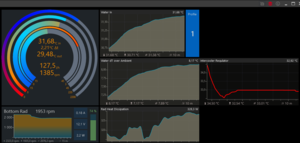
Here's a 15 minute sample:

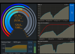
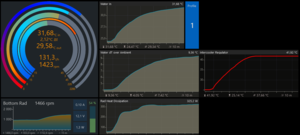
Here's from 6:30 PM to 9:15 PM: Note that the Intercooler Regulator (red) increases just before Coolant (Hot) [blue] registers an increase in temp. This was while playing a game, so the changes because of that. The intake temperature (green) is up and down because I have a window air conditioner in a room that needs new insulation. Controller output % is not depicted here, only the temperature reported by the Intercooler Regulator to feed the fan curves.

Here's the screenshot of the entire virtual sensor:

I made changes thanks to your earlier input that improved it, which I thank you for that assistance. I'm not forcing anyone to use it. I will post another log tomorrow showing the Intercooler Regulator, Hot Coolant temperature, Intake temperature, and Primary (Lian-Li fans 1,800 RPM max fan speed @ 100%) and Secondary (EK Vardar - 2,100 RPM max fan speed @ 100%) fan controller percentage (on separate curves due to RPM difference).
The upper calculations are not based on the air temperature. They are based entirely on the HOT coolant temperature. You saw that when you tested it the first time.
The lower calculations are based on the ambient air temperature average. This is a new thing to add a feedback that for a boost to fan speed should the temperature rises above room average. This is really only useful for smaller loops in poorly conditioned rooms. It was a suggestion made earlier by another member.
I've been running it since I updated it. It's been incredibly smooth. Note: The Intercooler Regulator feeds a fan curve. The curve is set between 0C and 40C with a 15 upward arch. A second curve also uses it, but has a 2 upward arch to account for RPM difference between fan types.
Here's a 15 minute sample:
Here's from 6:30 PM to 9:15 PM: Note that the Intercooler Regulator (red) increases just before Coolant (Hot) [blue] registers an increase in temp. This was while playing a game, so the changes because of that. The intake temperature (green) is up and down because I have a window air conditioner in a room that needs new insulation. Controller output % is not depicted here, only the temperature reported by the Intercooler Regulator to feed the fan curves.
Here's the screenshot of the entire virtual sensor:
I made changes thanks to your earlier input that improved it, which I thank you for that assistance. I'm not forcing anyone to use it. I will post another log tomorrow showing the Intercooler Regulator, Hot Coolant temperature, Intake temperature, and Primary (Lian-Li fans 1,800 RPM max fan speed @ 100%) and Secondary (EK Vardar - 2,100 RPM max fan speed @ 100%) fan controller percentage (on separate curves due to RPM difference).
weeeeeeell that jagged curve on your data viewer is super unstable
But as you installed the sensor on a fan intake, it makes sense. There's so much disturbance there, you can't get a stable reading without a lot of averaging (and lose responsiveness).
Why take the highest and lowest temperature of the room? the only temperature that matters is the one your radiators are intaking in real time. This is the only one that affects the radiator efficiency. real time water temperature, and real time air temperature.
If you calculate any other value, you are modulating fan speed based on a temperature that is not the one of the air they push, so it basically, by design, becomes either inefficient on the lower end, or needlessly noisy on the upper end.
This is where i have a problem with all the calculations. The most efficient cooling is always governed by dT. It is self regulating, winter or summer, smoothing is provided by the water thermal mass (you can introduce some more with averaging) but the more you deviate from that, the more inefficient/unstable the cooling becomes.
Maybe with air cooling several discrete components with independent cooling it can be useful, but with watercooling, i still fail to see the point
Dieser Beitrag wurde bereits 9 mal editiert, zuletzt von »Teknophage« (4. Oktober 2022, 09:14)
![]() Remayz
Remayz
Senior Member
uhm.. the sensor doesn't increase fan speed before the water temp on the graph, it either does nothing (staying flat because it never decreased fans speed when it should have) or lags behind every single time as i experienced.
All i see is a water temp that barely changes, and a fan curve that jumps all over the place instead of being as flat as the temperatures. Of course, that's masked by the very slight fan response because in absolute the control temp varies by little, but same deal : on a smaller loop with larger temp variations, and larger fan speed changes, the sensor will be noisy and very unstable.
All i see is a water temp that barely changes, and a fan curve that jumps all over the place instead of being as flat as the temperatures. Of course, that's masked by the very slight fan response because in absolute the control temp varies by little, but same deal : on a smaller loop with larger temp variations, and larger fan speed changes, the sensor will be noisy and very unstable.
Dieser Beitrag wurde bereits 1 mal editiert, zuletzt von »Remayz« (4. Oktober 2022, 10:15)
![]() Teknophage
Teknophage
Junior Member
I now understand your confusion. You're looking at the Intercooler Regulator as directly related to fan speed. The Intercooler Regulator is in degrees C. This is mapped to a controller that uses the output to regulate the fan speed based on the set curve. The fans do change accordingly, but only in 10ths of a percent or more depending on the curve and heat bloom. I have added charts dumped into Excel that may help understand the plotting. This chart includes fan speed (in percentage), the hot temperature, room temperature, and the Intercooler Regulator Temperature.uhm.. the sensor doesn't increase fan speed before the water temp on the graph, it either does nothing (staying flat because it never decreased fans speed when it should have) or lags behind every single time as i experienced.
All i see is a water temp that barely changes, and a fan curve that jumps all over the place instead of being as flat as the temperatures. Of course, that's masked by the very slight fan response because in absolute the control temp varies by little, but same deal : on a smaller loop with larger temp variations, and larger fan speed changes, the sensor will be noisy and very unstable.
Note that the increases were in 10ths of a percent, though jumps no more than 1% over time during this test. Depending on your fan curve, this could be negligible or it could be dramatic. That's tailorable. The regulator should be able to compensate if you set too low or high a curve.
Important note: My earlier recommendation to reduce the time on the Trend=X was incorrect and creates a problem. Increasing that time is best, providing earlier responsiveness when multiplied by 100. Decreasing the time on Trend=X works when removing the multiplier, but also causes more lag. Just finished testing that and confirmed it. What seems to happen is that it gets super sensitive at lower scales, making it inaccurate and delayed in this context. Increasing it makes changes very slight, but the multiplication brings out a quicker response to sudden change. Again, all confirmed, but would need more data to confirm in the field. This is what occurred which you noted in the earlier screenshot of the chart.
So to recap: Intercooler Regulator is an adjusted virtual temperature that maps to a controller, preferably curved but that's up to the user. It does relate to fans, but only changes the fan speed based upon your selected controller type and curve or set points. The changes in fan speed are slight on my system, but I did disable all fans but one rad's worth (the 60mm 360). I ran that test today but forgot to grab the data from it. It handled well, but again, this loop holds a bit more fluid, so I'd prefer to confirm function on a smaller loop.
While I'm looking at hot temperature in this, it doesn't depict the cold temperature. I don't want to set expectations on that, as milage may vary with smaller loops in comparison to mine. So you should compare function not only against how it manages fan speeds against the hot temperature, but also note if there's any changes to cold temperature as a result.
P.S. If you want specific information in another chart run, let me know and I'll produce it.

Dieser Beitrag wurde bereits 1 mal editiert, zuletzt von »Teknophage« (6. Oktober 2022, 04:52)
![]() Remayz
Remayz
Senior Member
Yes.. the regulator is directly related to fan speed. that's what a fan curve does. th fan curve will be a direct replicate of the temperature curve.
Yours is very flat because you did set it that way and as a consequence you basically heavily mask the defects of that sensor. with smooth fan curves, i can make the most discombobulated sensor look like the best thing since sliced bread
A steeper fan curve will just make a noisy mess. I mean look at your fan curve, it's not a curve it's a bar graph basically. it jumps values instead of transitionning smoothly as fan curves do. that is pure sound nuisance.
I still fail to see the relevance of the sensor. It doesn't control the fans well, it acts on imaginary temperatures (even if they are called hot/cold/ or "temperature map", they are not the real temp that the radiators are experiencing).
With such small temperature variations and a very gentle fan curve, you can't assess properly how the thing works or fails.
On my loop with 3 slim rads, and a 10900k and 3090, the thing was just bonkers. And from the graphs you showed, it still is. It just doesn't react well to heavy loads and faster temperature changes. And disabling 3 out of your 4 rads won't do much. there's just too much thermal mass in your loop, and not enough heat load to experience it. I mean you could set the fans to a quiet fixed speed and not even control them, it would work fine.
Take your last graph, and imagine the PWM% variations do not span 1% but 20%. you'll see what i mean.
![]() Teknophage
Teknophage
Junior Member
The variations are under 1%, in 10ths of a percent. If yours was "bonkers", then provide graphs. There are no defects in the sensor. It's working fine. I've been using it without problems. Fans are stable and quiet at idle 850 RPM. I've provided enough graphs showing only 10ths of a percentage of change and 10ths of a percentage in temperature changes. You have not provided any useful information since the initial graphs.Yes.. the regulator is directly related to fan speed. that's what a fan curve does. th fan curve will be a direct replicate of the temperature curve.
Yours is very flat because you did set it that way and as a consequence you basically heavily mask the defects of that sensor. with smooth fan curves, i can make the most discombobulated sensor look like the best thing since sliced bread
A steeper fan curve will just make a noisy mess. I mean look at your fan curve, it's not a curve it's a bar graph basically. it jumps values instead of transitionning smoothly as fan curves do. that is pure sound nuisance.
I still fail to see the relevance of the sensor. It doesn't control the fans well, it acts on imaginary temperatures (even if they are called hot/cold/ or "temperature map", they are not the real temp that the radiators are experiencing).
With such small temperature variations and a very gentle fan curve, you can't assess properly how the thing works or fails.
On my loop with 3 slim rads, and a 10900k and 3090, the thing was just bonkers. And from the graphs you showed, it still is. It just doesn't react well to heavy loads and faster temperature changes. And disabling 3 out of your 4 rads won't do much. there's just too much thermal mass in your loop, and not enough heat load to experience it. I mean you could set the fans to a quiet fixed speed and not even control them, it would work fine.
Take your last graph, and imagine the PWM% variations do not span 1% but 20%. you'll see what i mean.
I'm running 3 slim rads and one fat boy, a Ryzen Threadripper 3960x, and a 2080 Super OC'd all on the same loop. My rig runs idle cold temp at 22.4~25.8 C at between 5 and 7 K DT with a room temp between 70F to 74F shown on the intake (w/AC running), higher on hot days, lower on colder. So if you want to flex how your rig is responding to it, then there's mine. I can push full load and hit 74 C on the CPU on a hot day, up to 10 C less on a cold day. All while using these sensors.
Dieser Beitrag wurde bereits 6 mal editiert, zuletzt von »Teknophage« (7. Oktober 2022, 07:29)
![]() Remayz
Remayz
Senior Member
If you can't see the defects in your sensor from your own graphs then what is there to show? you already have them.
I told you, because you have a fat loop, very small thermal load in comparison, your fan curve is very flat, so you don't hear how bad it is since your fans speed vary very little.
just look at the bar graph your fan speed is, now apply that to a more steep curve and you'll get it.
Read my last phrase in the previous response, you'll understand why your sensor is unuseable unless you are deaf, or have a loop like yours with relativelylow load and huge thermal mass.
Your sensor has defects everywhere. it is not smooth, depending on the fan curve it is annoying sound wise, accelerating and decelerating fans steeply, it's noisy again because it doesn't reduce fan speeds quick enough when load decreases it lags behind thermal load, and it is very inefficient since it regulates fan speed based off virtual temperatures instead of real ones.
The way you implemented in your loop hides all those flaws, again because of your very flat fan curve.
I'm not going to lose time making graphs since you already showed them. It only takes a little bit of imagination to see what that sensor response curve does on a steeper fan curve. speed jumping 5-10% every 5 minutes constantly.
Now if you want to defend that sensor as the best thing ever made, you do you, i was just trying to help you see it does worse than a simple sensor with only two inputs and a substraction.
![]() Teknophage
Teknophage
Junior Member
Please provide graphs and data to demonstrate. Otherwise, your comments about it are just your opinion. You're refusing to provide information to support your claims. You inaccurately depicted a 20% variance without disclosing that the variance is within 10ths of a percent. I've provided plenty of evidence that shows that my loop is identical to yours, minus one radiator, and have provided information showing that the fans remain stable.If you can't see the defects in your sensor from your own graphs then what is there to show? you already have them.
I told you, because you have a fat loop, very small thermal load in comparison, your fan curve is very flat, so you don't hear how bad it is since your fans speed vary very little.
just look at the bar graph your fan speed is, now apply that to a more steep curve and you'll get it.
Read my last phrase in the previous response, you'll understand why your sensor is unuseable unless you are deaf, or have a loop like yours with relativelylow load and huge thermal mass.
Your sensor has defects everywhere. it is not smooth, depending on the fan curve it is annoying sound wise, accelerating and decelerating fans steeply, it's noisy again because it doesn't reduce fan speeds quick enough when load decreases it lags behind thermal load, and it is very inefficient since it regulates fan speed based off virtual temperatures instead of real ones.
The way you implemented in your loop hides all those flaws, again because of your very flat fan curve.
I'm not going to lose time making graphs since you already showed them. It only takes a little bit of imagination to see what that sensor response curve does on a steeper fan curve. speed jumping 5-10% every 5 minutes constantly.
Now if you want to defend that sensor as the best thing ever made, you do you, i was just trying to help you see it does worse than a simple sensor with only two inputs and a substraction.
I mean, unless your whole argument is that fan RPMs are always steady and have no fluctuation or variance at all...
Also, my fan curve is not flat. First post shows the curve. You're also making an assumption of relatively low load. I've tested this under full load, and I routinely use my system under full load for rendering, encryption, and much more. You're making generalizations and assumptions that have no backing given the information I've posted.
Dieser Beitrag wurde bereits 3 mal editiert, zuletzt von »Teknophage« (9. Oktober 2022, 17:51)
![]() Remayz
Remayz
Senior Member
you seem to only consider feedback that goes your way, and refuse feedback that shows your sensor doesn't work well..
by the way you added an input called "Hour" that is in fact a temperature. No idea what that is.
nevermind, it's the hour of the day. still no idea what it does in a cooling sensor.
by the way you added an input called "Hour" that is in fact a temperature. No idea what that is.
nevermind, it's the hour of the day. still no idea what it does in a cooling sensor.
Dieser Beitrag wurde bereits 1 mal editiert, zuletzt von »Remayz« (9. Oktober 2022, 19:30)
![]() Remayz
Remayz
Senior Member
Well.. setting up the cooling exactly as you do is quite the adventure.
Your fan curve ensures the fans run between 80 and 100% speed all the time. Indeed it cools well but who likes sitting next to a turbine?
Setting the curve to 0 arch makes it quieter but it's still a good 64% speed at idle which is too much. that's what i have at full load usually.
at + 13 i have something decent, but that only makes the fan acceleration noisier since they reach over 2000 RPM in a matter of seconds. And when stopping the load, the sensor holds that racket for minutes... off we go to reset the sensor..
I've made a curve that would make sense if i wasn't using dT, just based off water temp. the coolant never goes below 20°C, and as you i keep 40°C as full speed.
No arch, straight curve, otherwise it's too noisy at idle, and already, the fans run too fast at 50% PWM.
That's a bonus for you, i already push the cooling from the start.
25% at 20°C, 100% at 40°C, no arch.
Starting a game, the fans take off quickly because, despite the water being at 28, the sensor goes to 36 - 37 on the fan curve. Since the radiators aren't even that warm, it only causes noise and has no cooling benefit yet.
Now in less than 3 minutes, my fans are at 94% PWM because the sensor drives them as if the water was 38.3°C.

The water temp keeps climbing obviously since the 3090 is pushing over 350W but i'm being blasted by 2400 rpm fans while just following the water temp (no virdual sensor) they would be gently climbing around 65 - 70%.
What should i do ? make an arched curve? that would be even steeper accelerations and more nuisances. Raise the max temperature? I shouldn't have to if i want to limit the water temp to 40°C, but your sensor just uses "imaginary" temps, so i can't set a curve based off real temps. Right now the water stabilizes around 31, but the sensor keeps 38.
While i was typing that, the speeds dropped 10% because the sensor finally left its plateau.
But guess what? dropping that fast, the RTX does what it does best, the water temp goes back upand the fan speeds too.
Now the water is at 31.5, and the sensor at 33 which is closer to reality.
Usually under full load, my fans run close to 1700 rpm, right now they are just under 2000. i won't lose hours trying to get a similar result, it's close enough.
Waiting for the water to cool down, again, the sensor lags behind and keeps the PC noisy. the water is back to the temp i started (around 24) at but the fans are still at 70% because the sensors holds a 32°C temp.
And again, as i write that, the sensor drops and the fans slow down fast, and i have to stop the test there because the PC is chilling me, blowing air so hard on my side..
The point stands :
Your fan curve, that i completely missed from the first post, is what makes you believe you sensor is useable.
If you are at 90% PWM at idle, of course the sensor will work. those big swings will be so small you won't even notice them, but nobody does a curve like that. it's just too noisy, it clogs dust filters too fast and it defeats the purpose of having a fan controller. you could set a fixed 80 or 90% and be done.
With such a fan curve you can't assess at all how your sensor works. You are basing your own conclusions off a test that is basically rigged to succeed everytime, since no fan control is needed once your base speed is so fast..
You could make the most ridiculous sensor using every single module available in the playground and still have good temps.
You are using Vardars, they have a 0RPM feature, so, let's disregard it and try using your controller, varying your fan speed between 26% at whatever your water idle temp is, and 100% at 40°C. See what it does.
Now when you use delta T (which i remind you is a one operation virtual sensor) you get something like this :
the fan speed increases gradually, you barely notice it, and it follows the radiator efficiency which, again, is directly red as the water over ambient temperature difference.
This alone dictates how efficient your radiators are at dissipating heat. Blasting the fans while that delta is low only makes noise and has NO cooling benefit, none, at all.
This is why using imaginary calculated temperatures makes absolutely no sense. you disregard the one value that governs radiator efficiency and provides the best base for fan control.
Now if you want to manipulate that value to have a different fan curve between 8 AM and 10 PM, have fun but i'll maintain that the fan curve you used is too extreme to warrant the use of any control variable, and the virtual sensor is way too unstable and extremely inefficient at cooling if you use any fan curve that doesn't pierce your ears constantly at idle.
Your fan curve ensures the fans run between 80 and 100% speed all the time. Indeed it cools well but who likes sitting next to a turbine?
Setting the curve to 0 arch makes it quieter but it's still a good 64% speed at idle which is too much. that's what i have at full load usually.
at + 13 i have something decent, but that only makes the fan acceleration noisier since they reach over 2000 RPM in a matter of seconds. And when stopping the load, the sensor holds that racket for minutes... off we go to reset the sensor..
I've made a curve that would make sense if i wasn't using dT, just based off water temp. the coolant never goes below 20°C, and as you i keep 40°C as full speed.
No arch, straight curve, otherwise it's too noisy at idle, and already, the fans run too fast at 50% PWM.
That's a bonus for you, i already push the cooling from the start.
25% at 20°C, 100% at 40°C, no arch.
Starting a game, the fans take off quickly because, despite the water being at 28, the sensor goes to 36 - 37 on the fan curve. Since the radiators aren't even that warm, it only causes noise and has no cooling benefit yet.
Now in less than 3 minutes, my fans are at 94% PWM because the sensor drives them as if the water was 38.3°C.
The water temp keeps climbing obviously since the 3090 is pushing over 350W but i'm being blasted by 2400 rpm fans while just following the water temp (no virdual sensor) they would be gently climbing around 65 - 70%.
What should i do ? make an arched curve? that would be even steeper accelerations and more nuisances. Raise the max temperature? I shouldn't have to if i want to limit the water temp to 40°C, but your sensor just uses "imaginary" temps, so i can't set a curve based off real temps. Right now the water stabilizes around 31, but the sensor keeps 38.
While i was typing that, the speeds dropped 10% because the sensor finally left its plateau.
But guess what? dropping that fast, the RTX does what it does best, the water temp goes back upand the fan speeds too.
Now the water is at 31.5, and the sensor at 33 which is closer to reality.
Usually under full load, my fans run close to 1700 rpm, right now they are just under 2000. i won't lose hours trying to get a similar result, it's close enough.
Waiting for the water to cool down, again, the sensor lags behind and keeps the PC noisy. the water is back to the temp i started (around 24) at but the fans are still at 70% because the sensors holds a 32°C temp.
And again, as i write that, the sensor drops and the fans slow down fast, and i have to stop the test there because the PC is chilling me, blowing air so hard on my side..
The point stands :
Your fan curve, that i completely missed from the first post, is what makes you believe you sensor is useable.
If you are at 90% PWM at idle, of course the sensor will work. those big swings will be so small you won't even notice them, but nobody does a curve like that. it's just too noisy, it clogs dust filters too fast and it defeats the purpose of having a fan controller. you could set a fixed 80 or 90% and be done.
With such a fan curve you can't assess at all how your sensor works. You are basing your own conclusions off a test that is basically rigged to succeed everytime, since no fan control is needed once your base speed is so fast..
You could make the most ridiculous sensor using every single module available in the playground and still have good temps.
You are using Vardars, they have a 0RPM feature, so, let's disregard it and try using your controller, varying your fan speed between 26% at whatever your water idle temp is, and 100% at 40°C. See what it does.
Now when you use delta T (which i remind you is a one operation virtual sensor) you get something like this :
the fan speed increases gradually, you barely notice it, and it follows the radiator efficiency which, again, is directly red as the water over ambient temperature difference.
This alone dictates how efficient your radiators are at dissipating heat. Blasting the fans while that delta is low only makes noise and has NO cooling benefit, none, at all.
This is why using imaginary calculated temperatures makes absolutely no sense. you disregard the one value that governs radiator efficiency and provides the best base for fan control.
Now if you want to manipulate that value to have a different fan curve between 8 AM and 10 PM, have fun but i'll maintain that the fan curve you used is too extreme to warrant the use of any control variable, and the virtual sensor is way too unstable and extremely inefficient at cooling if you use any fan curve that doesn't pierce your ears constantly at idle.
![]() cptninc
cptninc
Full Member
This is what outputs are supposed to look like. The labels are scattered but will make more sense if you read them in order.
Note that this is done with the simple PID controllers built into the Aquaero using nothing more than the default "Normal" preset. It does not require the unreliable Aquasuite service (sorry, someone had to say it) in order to operate.
Compared to mess presented by the OP, this method is:


Note that this is done with the simple PID controllers built into the Aquaero using nothing more than the default "Normal" preset. It does not require the unreliable Aquasuite service (sorry, someone had to say it) in order to operate.
Compared to mess presented by the OP, this method is:
- Much more reliable
- Much more robust
- Much smoother
- Much quieter
- Much easier to tune and adjust
- Much easier to implement
- Does not require retuning every time a component is changed (not even if the entire PC is changed)

![]() Teknophage
Teknophage
Junior Member
"you seem to only consider feedback that goes your way, and refuse feedback that shows your sensor doesn't work well.."
No. I have at every instance been asking you to provide more information than opinion. You haven't provided any meaningful information I can review until now.
"you added an input called ' hour' that is in fact a temperature"
No, it's an hour. Hour = hour. One is set at 2 AM, the other is set at 2 PM. The sensor attached is connected to Aquasuite's Hour attribute. Another instance of hasty generalizations and assumptions...
"nevermind, it's the hour of the day. still no idea what it does in a cooling sensor"
You don't understand how an hour = an hour to cause a trigger to fire? If you trace the connections, you'll see that it triggers a memory module to record the max and low temperatures for that day and save them to disk. It then connects that temperature to find the average and use that number as a "bump" to fan speed on warmer days. NOTE: This is completely optional and all you need do is set the set-point temperature to your comfortable room temperature. The bump it creates, regardless, is very small.
I'm presently reviewing the information you finally posted, and will test. I have tested my fans at lower speeds using the original sensor, but not the updated one based on your earlier findings. I'll compare the two, however as intended, increasing the fan speeds to what is needed when hot temperature increases and decreasing them accordingly. It's supposed to be running fans faster when the temperature increases. The issue is that you're seeing a jump from 28F to 32F on the sensor and I don't see what you set your fan curve to as part of the information you sent over. Changing the curve lower will increase temperatures and increases the swing to quickly cool the system, but will return those fans to the lower.
Please send over a screenshot or the degree of arch used in the curves you used. I think you provided one example, so I'm testing that.
you seem to only consider feedback that goes your way, and refuse feedback that shows your sensor doesn't work well..
by the way you added an input called "Hour" that is in fact a temperature. No idea what that is.
nevermind, it's the hour of the day. still no idea what it does in a cooling sensor.
Dieser Beitrag wurde bereits 3 mal editiert, zuletzt von »Teknophage« (10. Oktober 2022, 20:08)
![]() Teknophage
Teknophage
Junior Member
Preliminary -- Your note about the "lags behind" aspect when the water has began to drop in temperature is by design. There is a maximum in place that holds the highest temperature recorded during the past 5 minutes Once the temperature began to drop, 5 minutes later, it would follow. This was intentional in the event another heat increase occurred, so it wouldn't have to chase the curve again and keep the cooling longer.
You CAN lower that time. In fact, if you want to play with the settings, feel free to do so. If you want it to follow the curve more closely, I believe 5 seconds is the lowest Aquasuite will go. Alternatively, if you want it to chase the curve, bypass/remove the max hold completely. It's the gold one on the far right. I caution here because while it chases the water's cooling downward rapidly, the water will also take longer to cool. My recommendation is to set something shorter that you're comfortable with -- a minute was the lowest I've used in the past.
On the note regarding the difference between hot water temp and the intercooler regulator temp, again, this is by design. It saw the direction your heat bloom was taking and anticipated where it might land. If the reaction to the landing maximum was too long, lowering the max hold time in seconds is recommended. Try a 60s hold.
Regarding the "reset the sensor" -- I don't advise this under load. The sensor is intended to capture the low and high on heat to determine how much to bump the fans in response to the increase in temperature. This does not indicate what your COLD temperature is. Your cold temperature reaction is completely different following the radiators, I don't know as it's not included in these screenshots.
That said, I'm testing against your information and will respond back within a day or two. I intend to run it over a couple of days at a lower fan speed. For the record: My fans normally run 74%, not 80+, except when my system is under heavy load. Do note that the lower your fan curve, the higher the regulator will presume it needs to go to get the fans to cool the increased heat, but it will rebound lower. It may fluctuate more as a result also, which is something that I need to investigate further given the revamp. The earlier version did not have that reaction, but perhaps the revamped version does. Again: Try setting the MAX HOLD to < 5 minutes. If you want to chase the temperature drop curve, that's your call.
Addendum: Fan noise -- I don't use the 0RPM feature of the Vardars. The Lian-Li max at 1800 and the EKs at 2200. The Lian-Li curve is lowered to match the EKs when they're at 1800~ish (the Lian-Li's maximum). Where they intersect can hold the Lian-Lis much higher, but typically, they sit around 840~ish, which the EKs also sit about 860ish.
One important thing I noticed about your loop was your pump speed. It's pushing .55 GPM, which is quite low and indicates your loop is as restrictive as mine. I did have to add a second DDC pump to get above 1 GPM. You'll note that Martin's Liquid Lab contains a lot of information about why you should be closer to 1 GPM and reviews several tops: http://martinsliquidlab.petrastech.com/D…TopTesting.html. If you're using a D5, that still low and your thin rads are likely causing it more than the GPU's waterblock. I understand you're sensitive to noise, so I recommend that if you do consider adding a second DDC to look at the HeatKiller IV multi-pump top. This is assuming your reservoir is decoupled from your pump. If not, then there's a HeatKiller IV of the same type that runs very quiet when combined with the EK DDC pump bottom (chrome or acetate). The rubber feet work well, but if you have space that doesn't impact airflow then the shoggy pad would be best to reduce vibration noise further.
Well.. setting up the cooling exactly as you do is quite the adventure.
Your fan curve ensures the fans run between 80 and 100% speed all the time. Indeed it cools well but who likes sitting next to a turbine?
Setting the curve to 0 arch makes it quieter but it's still a good 64% speed at idle which is too much. that's what i have at full load usually.
at + 13 i have something decent, but that only makes the fan acceleration noisier since they reach over 2000 RPM in a matter of seconds. And when stopping the load, the sensor holds that racket for minutes... off we go to reset the sensor..
I've made a curve that would make sense if i wasn't using dT, just based off water temp. the coolant never goes below 20°C, and as you i keep 40°C as full speed.
No arch, straight curve, otherwise it's too noisy at idle, and already, the fans run too fast at 50% PWM.
That's a bonus for you, i already push the cooling from the start.
25% at 20°C, 100% at 40°C, no arch.
Starting a game, the fans take off quickly because, despite the water being at 28, the sensor goes to 36 - 37 on the fan curve. Since the radiators aren't even that warm, it only causes noise and has no cooling benefit yet.
Now in less than 3 minutes, my fans are at 94% PWM because the sensor drives them as if the water was 38.3°C.
The water temp keeps climbing obviously since the 3090 is pushing over 350W but i'm being blasted by 2400 rpm fans while just following the water temp (no virdual sensor) they would be gently climbing around 65 - 70%.
What should i do ? make an arched curve? that would be even steeper accelerations and more nuisances. Raise the max temperature? I shouldn't have to if i want to limit the water temp to 40°C, but your sensor just uses "imaginary" temps, so i can't set a curve based off real temps. Right now the water stabilizes around 31, but the sensor keeps 38.
While i was typing that, the speeds dropped 10% because the sensor finally left its plateau.
But guess what? dropping that fast, the RTX does what it does best, the water temp goes back upand the fan speeds too.
Now the water is at 31.5, and the sensor at 33 which is closer to reality.
Usually under full load, my fans run close to 1700 rpm, right now they are just under 2000. i won't lose hours trying to get a similar result, it's close enough.
Waiting for the water to cool down, again, the sensor lags behind and keeps the PC noisy. the water is back to the temp i started (around 24) at but the fans are still at 70% because the sensors holds a 32°C temp.
And again, as i write that, the sensor drops and the fans slow down fast, and i have to stop the test there because the PC is chilling me, blowing air so hard on my side..
The point stands :
Your fan curve, that i completely missed from the first post, is what makes you believe you sensor is useable.
If you are at 90% PWM at idle, of course the sensor will work. those big swings will be so small you won't even notice them, but nobody does a curve like that. it's just too noisy, it clogs dust filters too fast and it defeats the purpose of having a fan controller. you could set a fixed 80 or 90% and be done.
With such a fan curve you can't assess at all how your sensor works. You are basing your own conclusions off a test that is basically rigged to succeed everytime, since no fan control is needed once your base speed is so fast..
You could make the most ridiculous sensor using every single module available in the playground and still have good temps.
You are using Vardars, they have a 0RPM feature, so, let's disregard it and try using your controller, varying your fan speed between 26% at whatever your water idle temp is, and 100% at 40°C. See what it does.
Now when you use delta T (which i remind you is a one operation virtual sensor) you get something like this :
the fan speed increases gradually, you barely notice it, and it follows the radiator efficiency which, again, is directly red as the water over ambient temperature difference.
This alone dictates how efficient your radiators are at dissipating heat. Blasting the fans while that delta is low only makes noise and has NO cooling benefit, none, at all.
This is why using imaginary calculated temperatures makes absolutely no sense. you disregard the one value that governs radiator efficiency and provides the best base for fan control.
Now if you want to manipulate that value to have a different fan curve between 8 AM and 10 PM, have fun but i'll maintain that the fan curve you used is too extreme to warrant the use of any control variable, and the virtual sensor is way too unstable and extremely inefficient at cooling if you use any fan curve that doesn't pierce your ears constantly at idle.
Dieser Beitrag wurde bereits 1 mal editiert, zuletzt von »Teknophage« (10. Oktober 2022, 20:56)
![]() Remayz
Remayz
Senior Member
I didn't follow what the hour sensor was doing because it makes no sense to have a timer in a cooling sensor, that's all.
Who cares what temperature my room was yesterday? it's the temperature it sits at RIGHT NOW that affects cooling. So you can remove that memory shenanigan from the sensor. it serves no purpose.
By the way, in a hot day, you don't accelerate fans. Again, it is the delta between ambient and water that governs how much heat the rads can dissipate. if my room is at 35°C and the water at 37, guess what benefit i'll have to set my fans at full speed? none. 2°C, that's an idling computer.
That's why everyone uses dT. it auto adjusts without needing overcomplicated calculations and random high speeds.
And i gave you my fan curve in my post : 25% at 20°C, 100% at 40°C, no arch.
It's not hasty assumptions.. it's confusion about throwing useless stuff in a cooling sensor that only serve at making it unuseable.
My loop is prefectly fine keeping the temperatures low at 1500 RPM. Why does your sensor assume it is NEEDED to run them at 2300 rpm for the same result?
That is with a curve that has a maximum fan speed at 40°, yet the sensor sends them at that speed while the water temp isn't even half that. This is what i call inefficient and noisy from the start.
But if you don't know how to make a fan curve, why even bother make a sensor? and one as complicated and useless at that?
I mean, we're still here trying to help, probably because we're idiots at this point' but please, do not come and post your sensor as if it was the best non compromise thing ever done. and you tested it for one year without noticing it is just a massive flaw, from end to end. The fan curves, the sensor behaviour, nothing makes sense at all.
It's fine being new to watercooling, there's nothing wrong with that, but don't try to play expert with such a unuseable sensor. It's really embarassing.
just use common sense and look how cooling works on a radiator (yes, they are radiators, not intercoolers). only 3 factors play any role. water temperature, air temperature, and air flow through the thing (fan speed). two inputs, one output. Need more tweaking? direct PID control does that perfectly already.
The hour of the day, the temperature from yesterday, the truncated square root of the average coldest temp times the hottest temp squared isn't helpful. neither is blasting fans at full speed on cold water.
No need to review data really, just look at the response graph of the sensor, we both used the same one. it's all over the place, it doesn't cool better. It's just a convoluted brute force method that may work if it was an aircooled build.. even then it would still be noisy.
I mean, have fun, test again, review data, make graphs, but as long as you don't know how to assess their relevance in the context of cooling a PC, it won't be useful.
Who cares what temperature my room was yesterday? it's the temperature it sits at RIGHT NOW that affects cooling. So you can remove that memory shenanigan from the sensor. it serves no purpose.
By the way, in a hot day, you don't accelerate fans. Again, it is the delta between ambient and water that governs how much heat the rads can dissipate. if my room is at 35°C and the water at 37, guess what benefit i'll have to set my fans at full speed? none. 2°C, that's an idling computer.
That's why everyone uses dT. it auto adjusts without needing overcomplicated calculations and random high speeds.
And i gave you my fan curve in my post : 25% at 20°C, 100% at 40°C, no arch.
It's not hasty assumptions.. it's confusion about throwing useless stuff in a cooling sensor that only serve at making it unuseable.
My loop is prefectly fine keeping the temperatures low at 1500 RPM. Why does your sensor assume it is NEEDED to run them at 2300 rpm for the same result?
That is with a curve that has a maximum fan speed at 40°, yet the sensor sends them at that speed while the water temp isn't even half that. This is what i call inefficient and noisy from the start.
But if you don't know how to make a fan curve, why even bother make a sensor? and one as complicated and useless at that?
I mean, we're still here trying to help, probably because we're idiots at this point
' but please, do not come and post your sensor as if it was the best non compromise thing ever done. and you tested it for one year without noticing it is just a massive flaw, from end to end. The fan curves, the sensor behaviour, nothing makes sense at all.It's fine being new to watercooling, there's nothing wrong with that, but don't try to play expert with such a unuseable sensor. It's really embarassing.
just use common sense and look how cooling works on a radiator (yes, they are radiators, not intercoolers). only 3 factors play any role. water temperature, air temperature, and air flow through the thing (fan speed). two inputs, one output. Need more tweaking? direct PID control does that perfectly already.
The hour of the day, the temperature from yesterday, the truncated square root of the average coldest temp times the hottest temp squared isn't helpful. neither is blasting fans at full speed on cold water.
No need to review data really, just look at the response graph of the sensor, we both used the same one. it's all over the place, it doesn't cool better. It's just a convoluted brute force method that may work if it was an aircooled build.. even then it would still be noisy.
I mean, have fun, test again, review data, make graphs, but as long as you don't know how to assess their relevance in the context of cooling a PC, it won't be useful.
![]() Teknophage
Teknophage
Junior Member
The room averaging was recommended by another member which makes sense as how they described it. It does serve a purpose -- The average of the room helps the sensor determine the anticipated temperature changes over time.
Delta-T is fine if people want to use that. I'm not holding a gun to anyone's head to use the Intercooler Regulator. My sensor is predictive and provides better cooling without having to guess what is efficient for the radiators and fans I'm using.
"My loop is prefectly fine keeping the temperatures low at 1500 RPM. Why does your sensor assume it is NEEDED to run them at 2300 rpm for the same result?" -- You were just complaining about fan speed and noise. 1500 RPM is a lot. Your fans can go higher, which is great, but don't accuse me of running exceptionally high fan speeds because your percentages of maximum are higher different than mine. You just answered the question I was hoping to investigate by lowering my fan percentage to yours. If your fans max at 2300, while my EKs at 2200 and Lian-Lis at 1800, and I'm keeping them on average at 840~ish RPMs, my system is nearly 45% more quiet than yours with slower fan speeds, including while using the Intercooler Regulator. If I'm working and not putting full load, they'll hold at about 1,200 to 1,300 RPM, up to 1,500 RPM on warm days.
Why it's running so high on yours is due to the spike in temperature. Again, I recommend the lower max hold time. Your original curve should have worked given the same temperature range of 0-40C, without adjusting it, but in adjusting it, demonstrated that the regulator is doing what it is intended to do. Note that your changes in temperature were 2C and your fan speeds moved from about 2,300 to 1,800 on the second to last image.
Long story short: Your fans probably are low pressure airflow fans not suitable for radiator use like static pressure fans. >> https://www.windowscentral.com/static-pr…ht-fans-your-pc -- One point of note, the article talks about thick rads, but it's noted an issue with thin/slim rads because it's also the fin density not just the thickness.
I didn't follow what the hour sensor was doing because it makes no sense to have a timer in a cooling sensor, that's all.
Who cares what temperature my room was yesterday? it's the temperature it sits at RIGHT NOW that affects cooling. So you can remove that memory shenanigan from the sensor. it serves no purpose.
By the way, in a hot day, you don't accelerate fans. Again, it is the delta between ambient and water that governs how much heat the rads can dissipate. if my room is at 35°C and the water at 37, guess what benefit i'll have to set my fans at full speed? none. 2°C, that's an idling computer.
That's why everyone uses dT. it auto adjusts without needing overcomplicated calculations and random high speeds.
And i gave you my fan curve in my post : 25% at 20°C, 100% at 40°C, no arch.
It's not hasty assumptions.. it's confusion about throwing useless stuff in a cooling sensor that only serve at making it unuseable.
My loop is prefectly fine keeping the temperatures low at 1500 RPM. Why does your sensor assume it is NEEDED to run them at 2300 rpm for the same result?
That is with a curve that has a maximum fan speed at 40°, yet the sensor sends them at that speed while the water temp isn't even half that. This is what i call inefficient and noisy from the start.
But if you don't know how to make a fan curve, why even bother make a sensor? and one as complicated and useless at that?
I mean, we're still here trying to help, probably because we're idiots at this point
It's fine being new to watercooling, there's nothing wrong with that, but don't try to play expert with such a unuseable sensor. It's really embarassing.
just use common sense and look how cooling works on a radiator (yes, they are radiators, not intercoolers). only 3 factors play any role. water temperature, air temperature, and air flow through the thing (fan speed). two inputs, one output. Need more tweaking? direct PID control does that perfectly already.
The hour of the day, the temperature from yesterday, the truncated square root of the average coldest temp times the hottest temp squared isn't helpful. neither is blasting fans at full speed on cold water.
No need to review data really, just look at the response graph of the sensor, we both used the same one. it's all over the place, it doesn't cool better. It's just a convoluted brute force method that may work if it was an aircooled build.. even then it would still be noisy.
I mean, have fun, test again, review data, make graphs, but as long as you don't know how to assess their relevance in the context of cooling a PC, it won't be useful.
Dieser Beitrag wurde bereits 4 mal editiert, zuletzt von »Teknophage« (10. Oktober 2022, 21:26)
![]() Remayz
Remayz
Senior Member
For my pump it's fine thanks. the flow makes no difference in waterblock temperatures as long as it's above 80L/h (0.35 gpm). I'm running it too fast already and don't need to regulate the speed. Read again their test setup when they did the radiator tests, you'll understand why those values are not useful when talking about a real build VS a test setup.
Edit : nevermind i thought you talked about the radiator test VS flow rate. That article you linked is relevant to nothing in terms of cooling. they just compare pump tops.
Your fans on your screen caps were running at 90% PWM. that's not 850 rpm on a vardar. i used X3Ms for a year, thank you. your fan curve itself sits close to 90% at room temperature.
I know about static pressure fans too. the distinction between static pressure and airflow optimized has been around for a number of years you know?
My fans max out at 2600 RPM. They are quiet at 1500.
The problem with your sensor, no matter how hard you try to justify it is that it disregards radiator efficiency completely. Forget noise level. why does it make the fans skyrocket when the radiators can't dissipate heat? to achieve what?
when the water has cooled, why does it keep the fans running hard? to achieve what ?
Why does it use calculated estimations to regualte fan speed instead of what the PC is actually experiencing? what's the goal?
Do you understand the principle of radiator efficiency with air and water temperatures? you keep brushing over that but it's in the core of why your sensor is dysfunctional.
And on the last image i said it was a delta T sensor, that's why it worked as intended. That's my usual fan curve.
I left your sensor on the side but it wasn't controlling the fans. Yours is on the first image, 1800 RPM at 31°C. 2300 RPM was the second test.
Dieser Beitrag wurde bereits 1 mal editiert, zuletzt von »Remayz« (10. Oktober 2022, 21:33)
![]() Taubenhaucher
Taubenhaucher
God
I think the sensor will do exactly what the thread creator expects it to do and the expectations are in sync with the results over the course of the year.
Why argue further, you will not be able to convince him, he believes in his sensor.
The fact that you can achieve the same or better results with a modern motherboard, a few temperature sensors and the fan control in the bios will not convince him.
There are simply people who always have to reinvent the wheel.
That's OK, but please don't try to impress everyone else who has been dealing with the matter for years with concepts that have long been exposed as nonsense.
For the water cooling of a PC, common sense and a little bit of physics is enough.
Translated with www.DeepL.com/Translator (free version)
Es gibt keinen Ausweg, den ein Mensch nicht beschreitet, um die tatsächliche Arbeit des Denkens zu vermeiden.
Thomas Alva Edison (1847-1931), amerik. Erfinder
Thomas Alva Edison (1847-1931), amerik. Erfinder
Ähnliche Themen
-
 English forum »
-
 D5 Pump Speeds
(27. Juli 2022, 10:04)
D5 Pump Speeds
(27. Juli 2022, 10:04)
-
- English forum »
-
Leakshield and kryographics next rtx 2080 ti: pressure drops when GPU heats
(13. August 2021, 15:47)
-
- English forum »
-
MPS 400 flow meter durability
(28. Dezember 2016, 16:39)
-
- English forum »
-
VRM cooling blocks for ASUS A8N series
(26. Oktober 2005, 16:41)
-
- Off-Topic »
-
Katzenbabys - 10 1/2 Wochen S. 25
(8. November 2003, 07:38)
-