 16.06.2024, 10:09
 Sprache ändern
 Registrieren
 Anmelden
Sie sind nicht angemeldet.
Lieber Besucher, herzlich willkommen bei: Aqua Computer Forum. Falls dies Ihr erster Besuch auf dieser Seite ist, lesen Sie sich bitte die Hilfe durch. Dort wird Ihnen die Bedienung dieser Seite näher erläutert. Darüber hinaus sollten Sie sich registrieren, um alle Funktionen dieser Seite nutzen zu können. Benutzen Sie das Registrierungsformular, um sich zu registrieren oder informieren Sie sich ausführlich über den Registrierungsvorgang. Falls Sie sich bereits zu einem früheren Zeitpunkt registriert haben, können Sie sich hier anmelden.

- 1
- 2


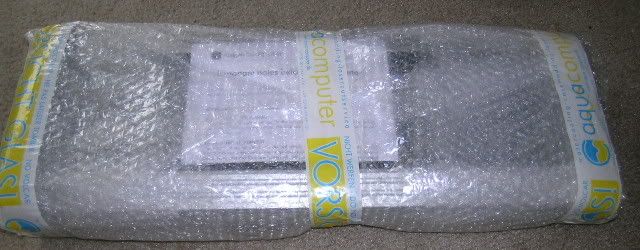
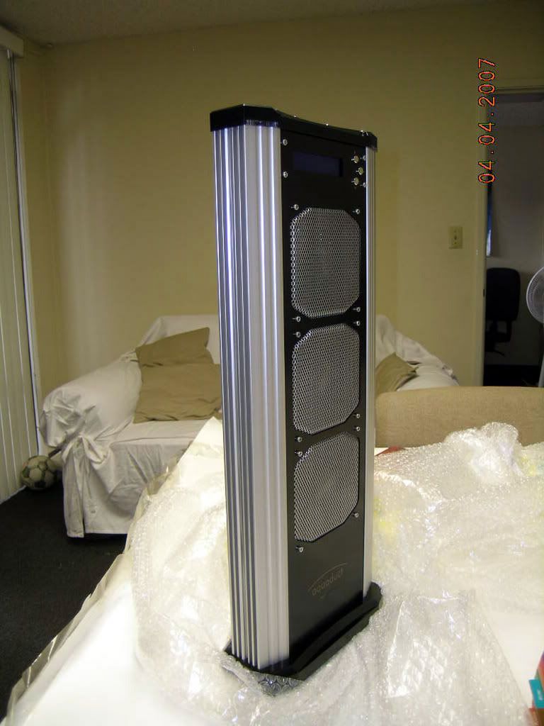
I know I have been interested in seeing the new AC Aquaduct so I suppose perhaps others might as well. It took a while to get the moula up as these go for about $550 here in the states (colonies for you brits), but I have one now. Now most people want to stick it into their rig to see how well it works. Since I take the road less traveled my first thought is to take it apart and do some modding. More on that later. So for now let's see what we get. This monster hunk of German engineering is really quite heavy even without water. I didn't weigh it (scales are bad to have in the house) but it appears to be about 20-30 lbs for the main unit.
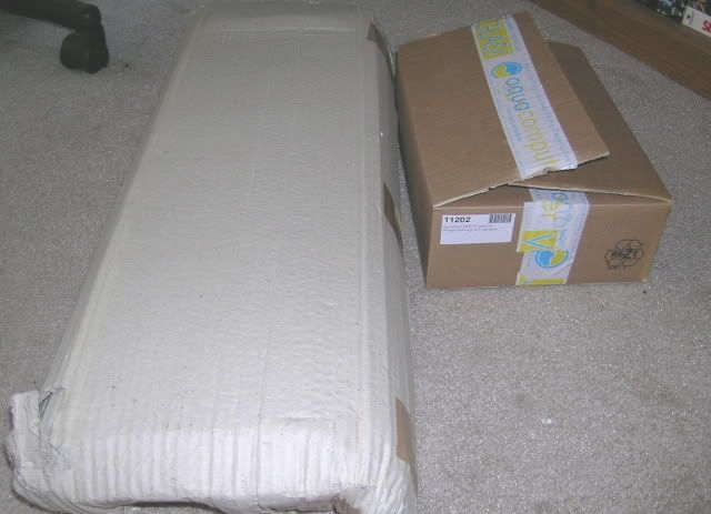
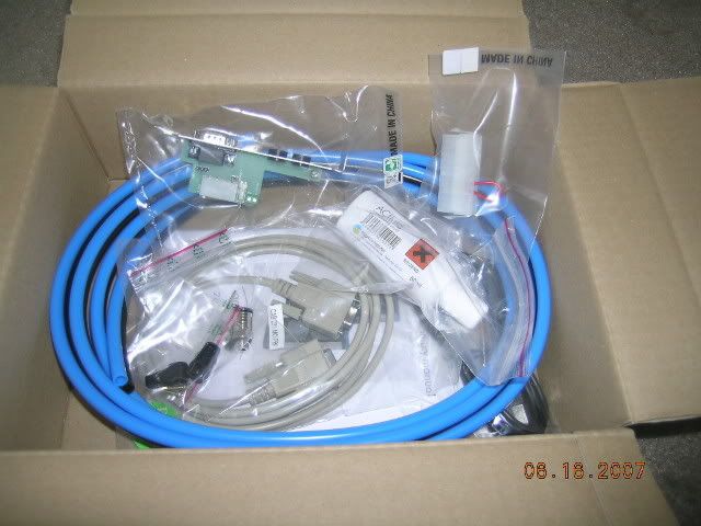
The rest of the stuff comes in the other box and seems to be well packaged for transport around the world.
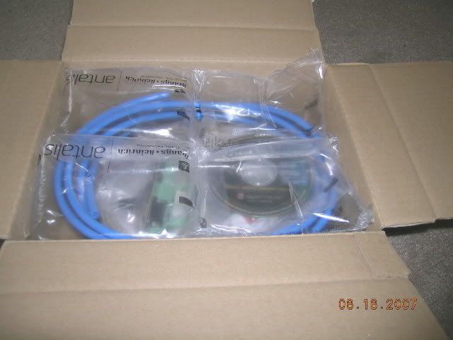
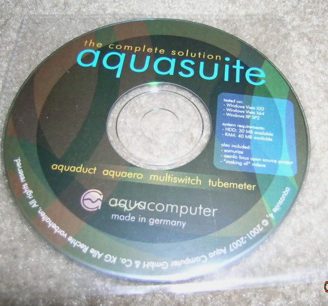
The first item here is the CD that comes in the box. You might not be able to see from the pic, but it has been tested on XP Sp 2; Vista x32, and Vista x64. If you happen to be a penguin fan they also have software for the Linux OS as well. In addition the CD also has Samurize and some videos showing the making of various AC components. One thing to keep in mind is that the software requires version 2 of the .NET framework. If you need software that will run on version 1 there are several back versions of the software you may find usable here at the Aqua Computer site. You can also find version 1 & 2 on the CD as well. One thing I forgot to mention is that the Aquasuite software comes with a SDK that is included on the CD as well for your modding pleasure.
You used to have to run the Aquasuite in the background if you wanted to use Samurize, but now someone has made a hack that allows you to print operating conditions directly to your screen without the Aquasuite being on.
Next you see the rest of the stuff in the box.
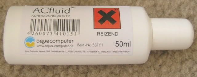
A bottle of AC Fluid. My math calculates about 343 ML of distilled water + 7 cc AC Fluid in my Feeding Frenzy Interlude project. So I figure you can make about 2.5 liters of coolant with this 50 cc bottle. From what I have been told the whole Aquaduct system (including blocks) holds about 2 liters of coolant.
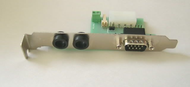
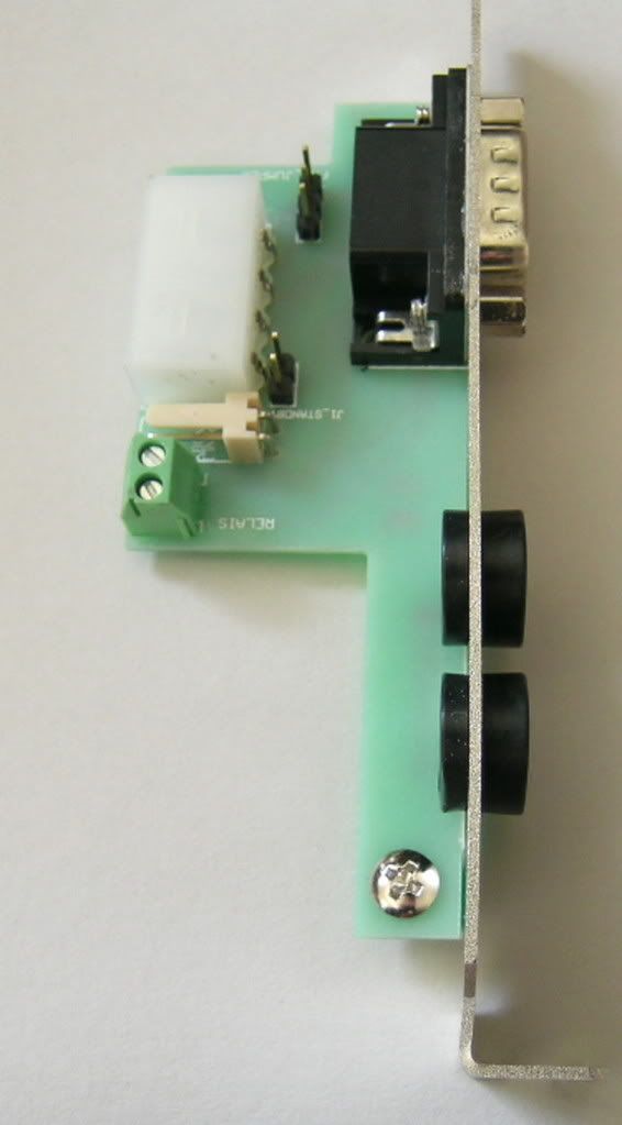
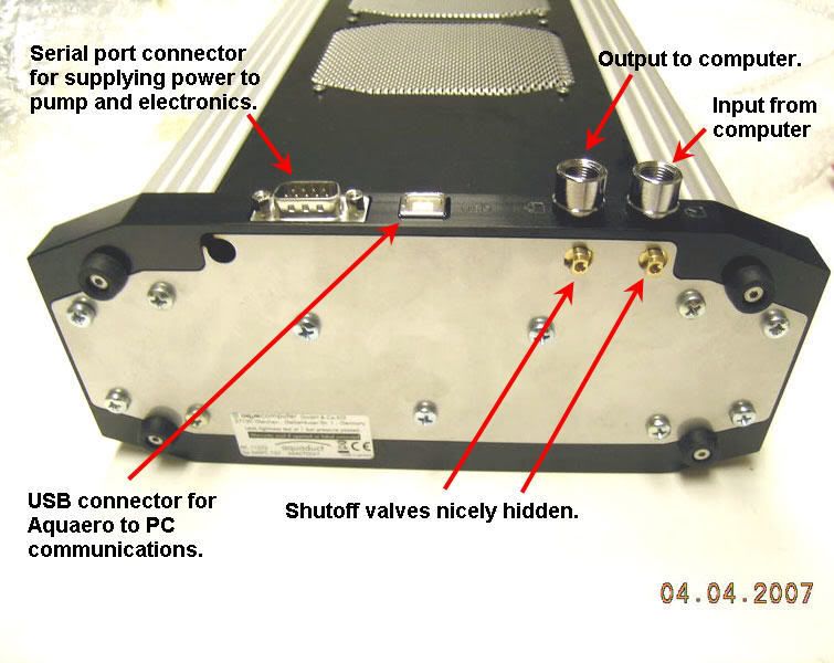
Here the slot device through which the hoses can go through your case into the computer. The serial is not really a serial port, but only to carry power to the Aquaduct and for some assorted accessory use in case you want to add standby power or a relay output to your ATX break line.
The rest of the stuff comes in the other box and seems to be well packaged for transport around the world.
The first item here is the CD that comes in the box. You might not be able to see from the pic, but it has been tested on XP Sp 2; Vista x32, and Vista x64. If you happen to be a penguin fan they also have software for the Linux OS as well. In addition the CD also has Samurize and some videos showing the making of various AC components. One thing to keep in mind is that the software requires version 2 of the .NET framework. If you need software that will run on version 1 there are several back versions of the software you may find usable here at the Aqua Computer site. You can also find version 1 & 2 on the CD as well. One thing I forgot to mention is that the Aquasuite software comes with a SDK that is included on the CD as well for your modding pleasure.
You used to have to run the Aquasuite in the background if you wanted to use Samurize, but now someone has made a hack that allows you to print operating conditions directly to your screen without the Aquasuite being on.
Next you see the rest of the stuff in the box.
A bottle of AC Fluid. My math calculates about 343 ML of distilled water + 7 cc AC Fluid in my Feeding Frenzy Interlude project. So I figure you can make about 2.5 liters of coolant with this 50 cc bottle. From what I have been told the whole Aquaduct system (including blocks) holds about 2 liters of coolant.
Here the slot device through which the hoses can go through your case into the computer. The serial is not really a serial port, but only to carry power to the Aquaduct and for some assorted accessory use in case you want to add standby power or a relay output to your ATX break line.
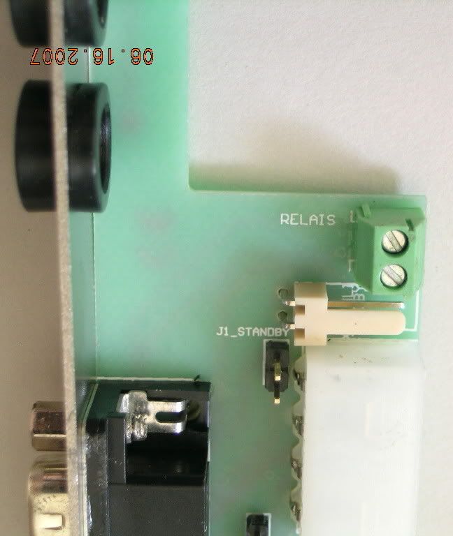
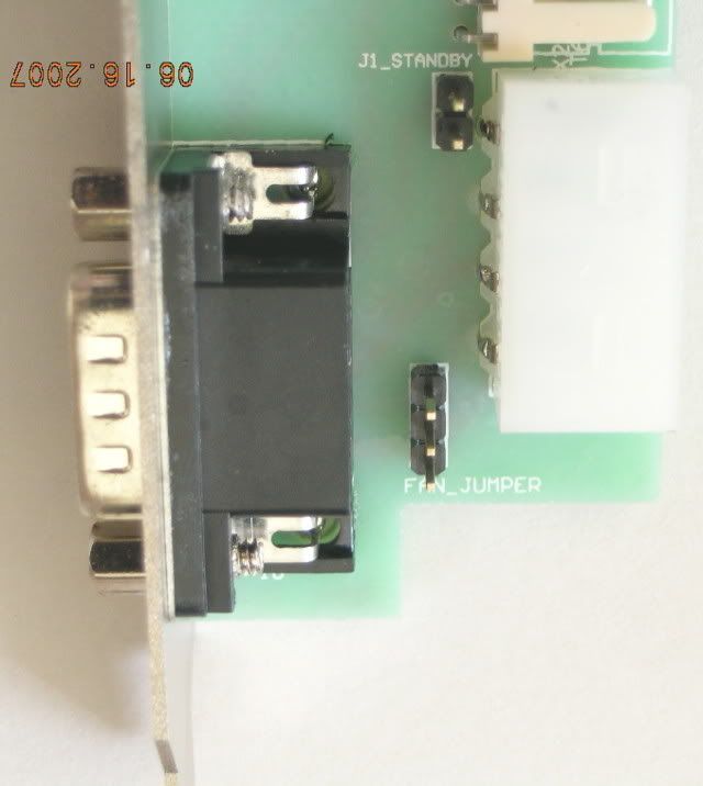
Some more closeup views of the circuit board.
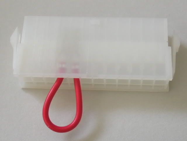
Here is something that always comes in AC kits and pumps. I know the paper clip routine is more ghetto, but this works well too. Don't let your friends see it or it will disappear.
These are the handles that go on the bottom of the Aquaduct to turn off and on the ball valves.
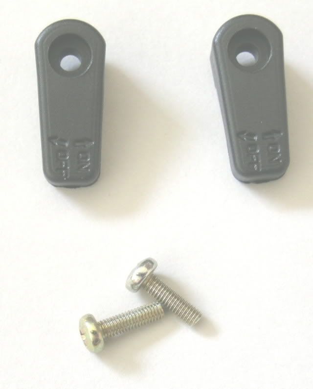
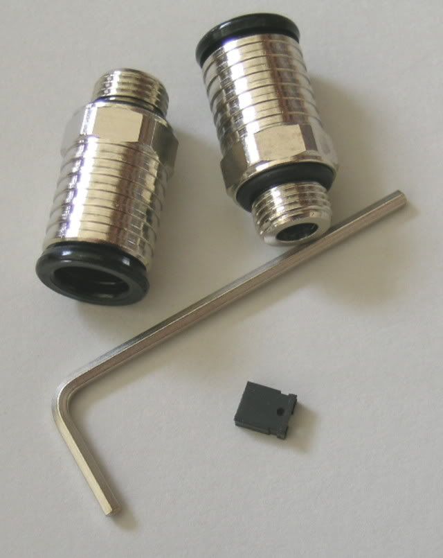
The next little bag is for the G 1/8 6mm x 8mm push-fit connectors. Don't lose the black pin connector! If your not using the standby power the Aquaduct fans will not work unless you have this! The hex key is to open the top so you can fill the unit. If your not into 6 x 8 tubing you can get up to 3/8" barbs through the web shop or any AC dealer.
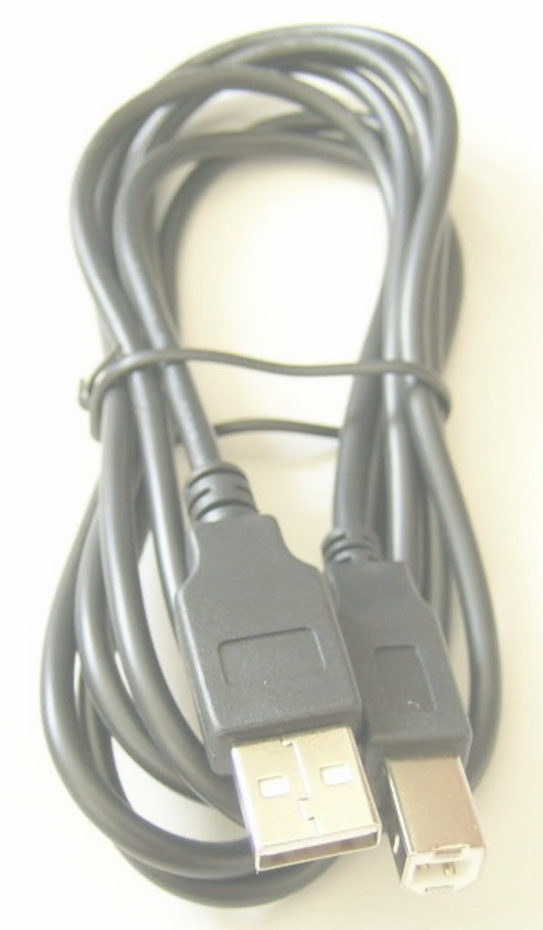
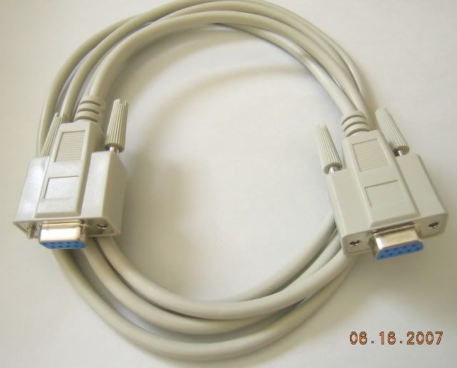
About six feet of USB and serial cables.
About 9 feet of what looks suspiciously like Legris PUR double tubing.

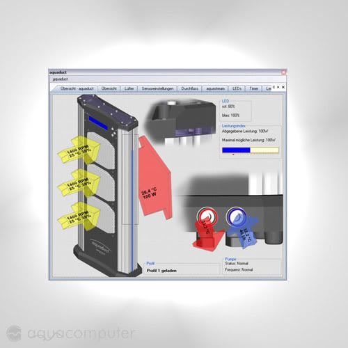
In case your wondering why the dual colors it has to do with making the install as painless as possible. See the screen shot below as it helps you make sure you get the intake and output right. Hooking it up ass backwards will probably result in you having to drain the system and refilling it to get all the air out.
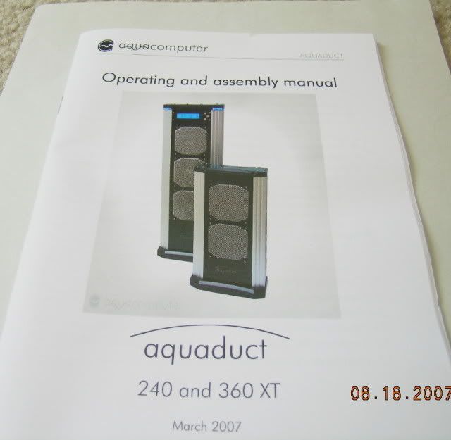
And of course what manufacturer doesn't include a nice full color manual with their products? One bow wow here as the box was supposed to have an Aquaero manual as well. I already have a couple of the manual's laying around but someone new to AC would have a fit trying to figure out how the electronics work. Fortunately the CD has all current manuals on it in both German and English.
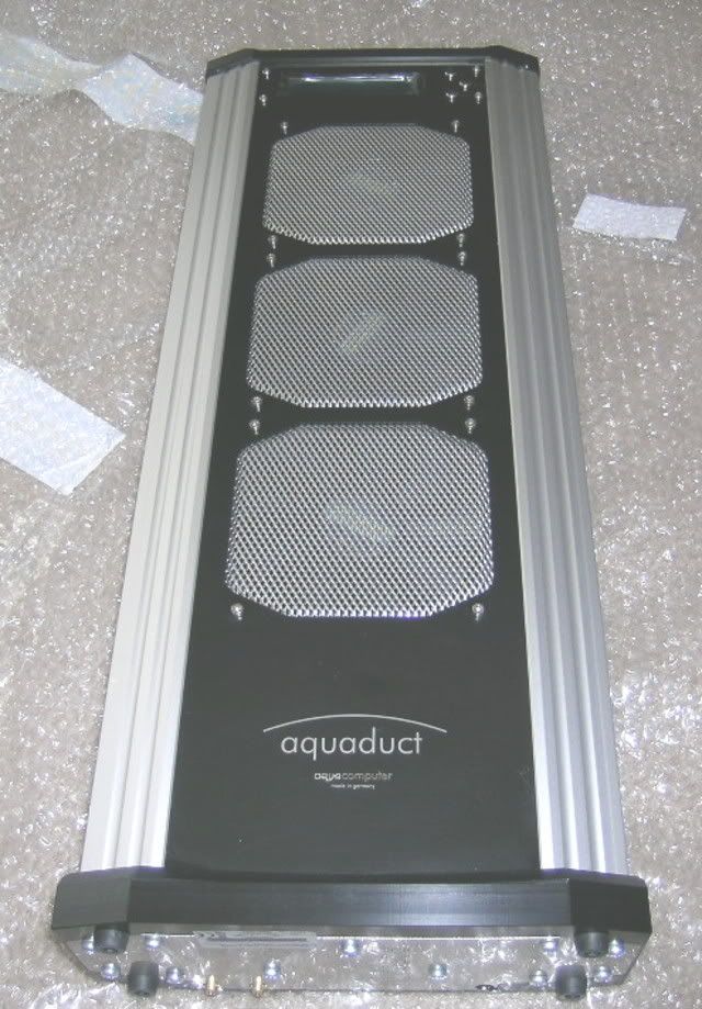
Getting back to the Aquaduct here are some more pics. The first one is a stock AC pic that shows the system lit up when it's running. I'm using the AC pic because it might be a while before I get this modded to my own liking. BTW, the reason they call it an Aquaduct is because the water comes up on the left and flows over the top bridge before falling down on the right side.
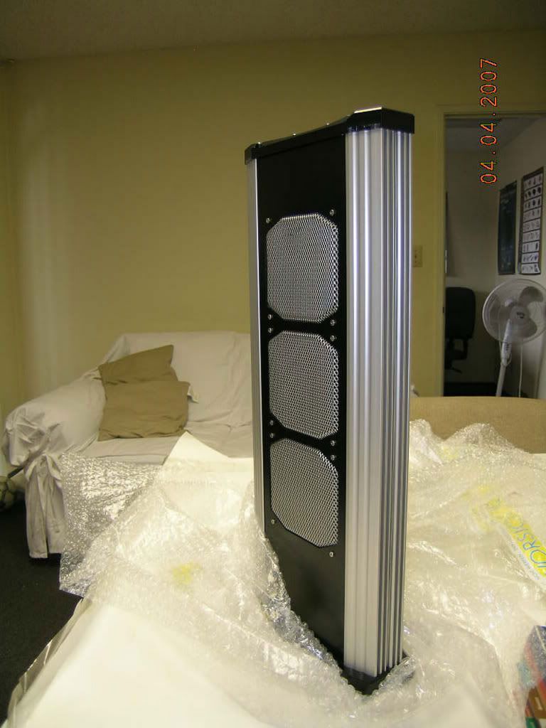
Here are the pics I shot a couple of months ago when Sharka put my Aquaduct on the lay-a-way plan.
Another bow wow here as I hate it when I'm not supposed to open little black boxes up. However, I guess when it's difficult to put together the manufacturer just wants it understood that they ain't paying to fix your inability to put it back together.
So here is where we get off till I get a chance to do some reverse engineering later this week. The three Aquaduct units (that I know of here in the states) that were taken apart were never successfully put back together and to a one they all leaked. So I took it up here on the AC English Forum and got some straight answers to my questions of how to disassemble it correctly from Stephan.
Tomorrow I will show you the disassembly technique and what's in the Aquaduct.
Here is something that always comes in AC kits and pumps. I know the paper clip routine is more ghetto, but this works well too. Don't let your friends see it or it will disappear.
These are the handles that go on the bottom of the Aquaduct to turn off and on the ball valves.
The next little bag is for the G 1/8 6mm x 8mm push-fit connectors. Don't lose the black pin connector! If your not using the standby power the Aquaduct fans will not work unless you have this! The hex key is to open the top so you can fill the unit. If your not into 6 x 8 tubing you can get up to 3/8" barbs through the web shop or any AC dealer.
About six feet of USB and serial cables.
About 9 feet of what looks suspiciously like Legris PUR double tubing.
In case your wondering why the dual colors it has to do with making the install as painless as possible. See the screen shot below as it helps you make sure you get the intake and output right. Hooking it up ass backwards will probably result in you having to drain the system and refilling it to get all the air out.
And of course what manufacturer doesn't include a nice full color manual with their products? One bow wow here as the box was supposed to have an Aquaero manual as well. I already have a couple of the manual's laying around but someone new to AC would have a fit trying to figure out how the electronics work. Fortunately the CD has all current manuals on it in both German and English.
Getting back to the Aquaduct here are some more pics. The first one is a stock AC pic that shows the system lit up when it's running. I'm using the AC pic because it might be a while before I get this modded to my own liking.
BTW, the reason they call it an Aquaduct is because the water comes up on the left and flows over the top bridge before falling down on the right side.Here are the pics I shot a couple of months ago when Sharka put my Aquaduct on the lay-a-way plan.
Another bow wow here as I hate it when I'm not supposed to open little black boxes up. However, I guess when it's difficult to put together the manufacturer just wants it understood that they ain't paying to fix your inability to put it back together.
So here is where we get off till I get a chance to do some reverse engineering later this week. The three Aquaduct units (that I know of here in the states) that were taken apart were never successfully put back together and to a one they all leaked. So I took it up here on the AC English Forum and got some straight answers to my questions of how to disassemble it correctly from Stephan.
Tomorrow I will show you the disassembly technique and what's in the Aquaduct.
So back to the Aquaduct. Last night I started the disassembly and here I have already taken off the blue plexi top.
One thing that is very important about the un-tightening sequence is that you must use a cross pattern and only a twist or two of the driver per sequence. This will became apparent later on as to the why.
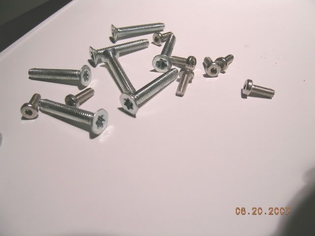
Make sure you bag up the screws as the flat head TORX screws may be hard to find in your locale.
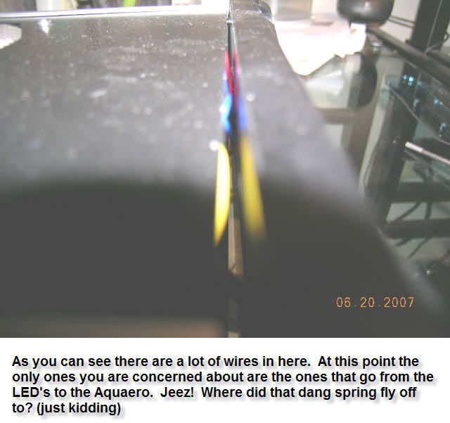
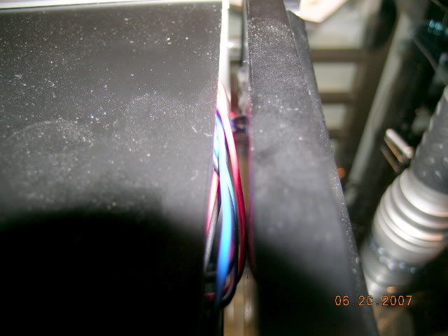
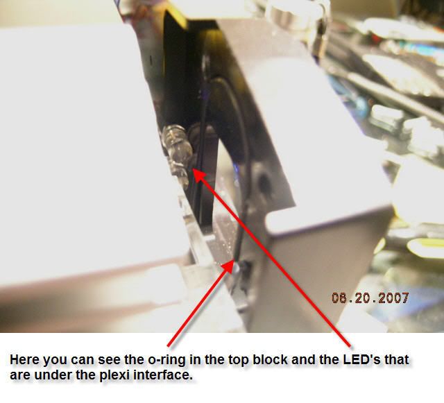
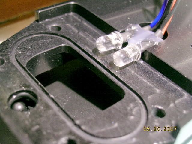
The wires you see here are the important ones to make sure you don't accidentally pull out of the top plate. These are the four (4) LED's that make up the blue glow you see in normal operation. These LED's can also be configured to glow red according to whatever temp you decide should be a visual warning.
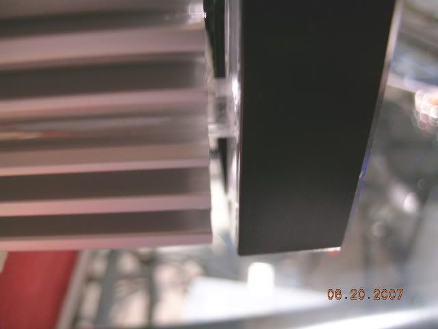
When I first pulled out the top plate a ways I wasn't sure how all this was connected together so I decided to take off the plexi plate that you can see fitted into the top plate. This is totally unnecessary so don't do what I did. However, the plus side is that you get to see more pics, right?
That plexi plate was really difficult to get out. If you decide to take it out you will need some dental probes, some jewelers screwdrivers, and maybe some kind of really thin piece of flat stock about 1.5" wide.
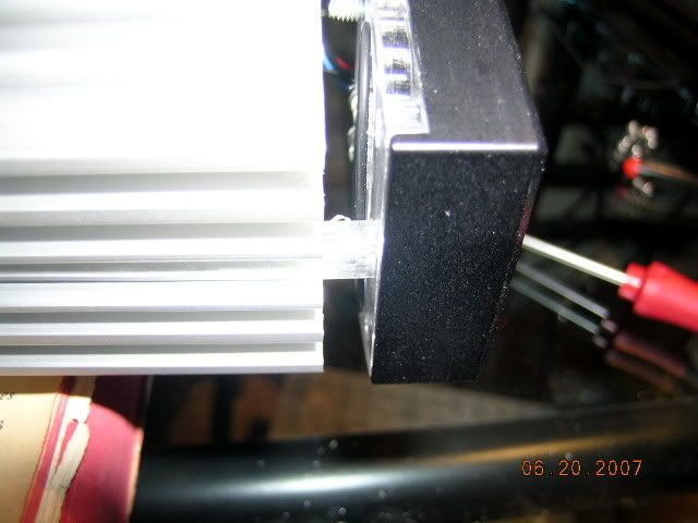
I finally got that dang plate out. Be careful you don't scratch it or you will be FUBAR as two o-rings seal against it.
One thing that is very important about the un-tightening sequence is that you must use a cross pattern and only a twist or two of the driver per sequence. This will became apparent later on as to the why.
Make sure you bag up the screws as the flat head TORX screws may be hard to find in your locale.
The wires you see here are the important ones to make sure you don't accidentally pull out of the top plate. These are the four (4) LED's that make up the blue glow you see in normal operation. These LED's can also be configured to glow red according to whatever temp you decide should be a visual warning.
When I first pulled out the top plate a ways I wasn't sure how all this was connected together so I decided to take off the plexi plate that you can see fitted into the top plate. This is totally unnecessary so don't do what I did. However, the plus side is that you get to see more pics, right?
That plexi plate was really difficult to get out. If you decide to take it out you will need some dental probes, some jewelers screwdrivers, and maybe some kind of really thin piece of flat stock about 1.5" wide.
I finally got that dang plate out. Be careful you don't scratch it or you will be FUBAR as two o-rings seal against it.
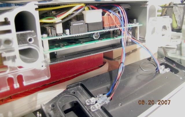
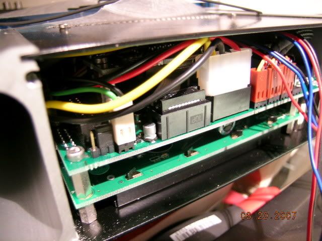
Now that I got the front plate off this is what is underneath it. For those in the know this looks like a pretty standard Aquaero circuit board, except for that big electrolytic capacitor just between the LCD board and the Aquaero board. Notice the sleeving on the fan wires? Now that's class to sleeve when no one will ever see it, huh?
Another odd thing is that you can see that they have the ribbon cable (to the left of the molex power connector) hooked up to something. Wonder what that is because AC has said that the Poweradjust unit can't be interfaced to the Aquaero and there certainly isn't an Aquastream in this Aquaduct. I guess we will see later what the surprise is.
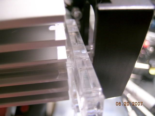
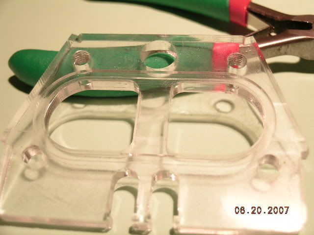
Here is one of the plexi plates. These also have an o-ring groove machined into it so that it seals against the aluminum side cooling extrusions.
I have been thinking about something here. See that gigantic flow chamber? I wonder how much extra flow you get from having that additional water cross section in the loop. That's 1.890" x 0.710" x about 23" x 2 sides plus the fairly wide water channel in the top plate.
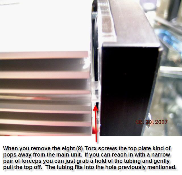
Remember when I suggested that you be very careful when unscrewing the Torx screws. Now you can see why I made the warning. The tapped holes are missing about 20% of their threads so creating a lateral force on the top while taking it off might FUBAR the threads. BTW, I would highly suggest that you cover that surface with some blue painters tape to protect that surface from scratches. O-rings don't like scratches.
Here's another pic of the top plate. Make sure you don't pull the LED's loose as they fit exactly into the plexi plate shown above.
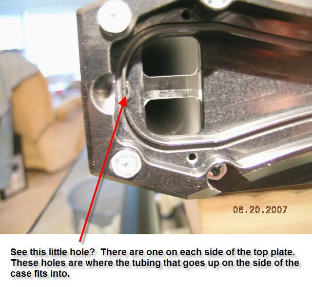
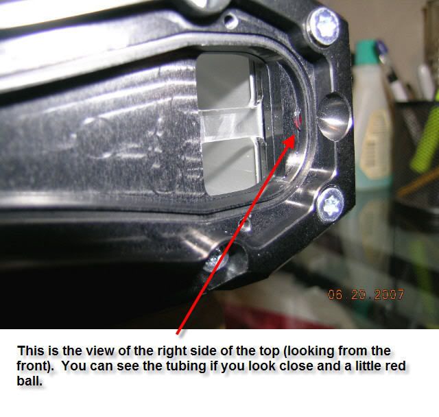
Hey, we got more cross sectional flow here add in another 6mm x 25" x 2 tubes.
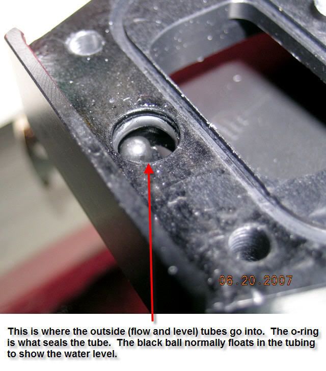
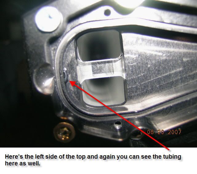
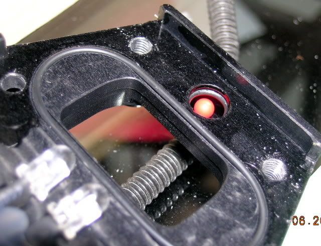
Here's the right side of the top plate. The little red ball only shows flow when you start up the Aquaduct. While it is in operation it sits up here in the top block.
The next job is to slide out the black plate you see at the top of the pic.
That's all for now till I take some more pics.
Another odd thing is that you can see that they have the ribbon cable (to the left of the molex power connector) hooked up to something. Wonder what that is because AC has said that the Poweradjust unit can't be interfaced to the Aquaero and there certainly isn't an Aquastream in this Aquaduct. I guess we will see later what the surprise is.
Here is one of the plexi plates. These also have an o-ring groove machined into it so that it seals against the aluminum side cooling extrusions.
I have been thinking about something here. See that gigantic flow chamber? I wonder how much extra flow you get from having that additional water cross section in the loop. That's 1.890" x 0.710" x about 23" x 2 sides plus the fairly wide water channel in the top plate.
Remember when I suggested that you be very careful when unscrewing the Torx screws. Now you can see why I made the warning. The tapped holes are missing about 20% of their threads so creating a lateral force on the top while taking it off might FUBAR the threads. BTW, I would highly suggest that you cover that surface with some blue painters tape to protect that surface from scratches. O-rings don't like scratches.
Here's another pic of the top plate. Make sure you don't pull the LED's loose as they fit exactly into the plexi plate shown above.
Hey, we got more cross sectional flow here add in another 6mm x 25" x 2 tubes.
Here's the right side of the top plate. The little red ball only shows flow when you start up the Aquaduct. While it is in operation it sits up here in the top block.
The next job is to slide out the black plate you see at the top of the pic.
That's all for now till I take some more pics.
Okay, time to do some more surgery. The next operation is to get the back panel off. To do this you have to take off all the 3mm fan screws. Two of the screws had the socket hex stripped. Not fun to have to get a pair of vice-grips out to get them off. Well no big deal as I plan on only using stainless button heads on re-assembly. ;D
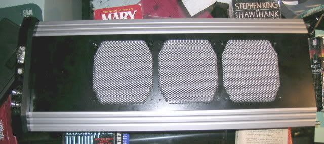
Here you can see me sliding off the back panel.
In case you were wondering how they did that fancy grill this is it. AC has started selling this grill in some pre-made cases so I think it is only a matter of time before they sell them by themselves.
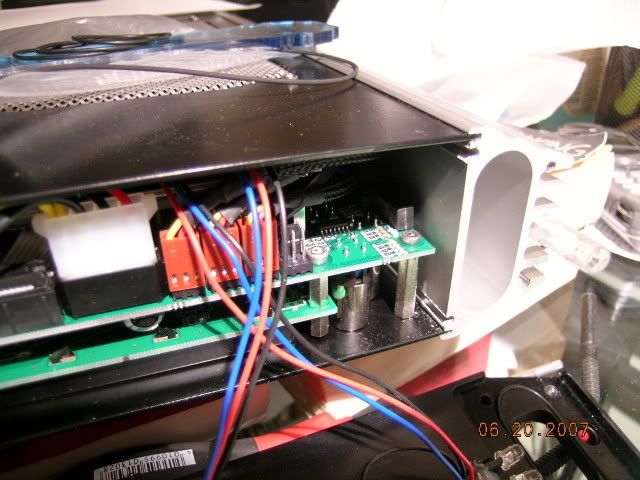
Here's looking at the bottom inside of the Aquaduct.
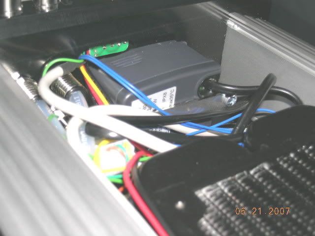
Here you can see the Eheim Compact 600 pump and the DigMesa flow meter is barely visible under the tubing on the right side. I take back what I said earlier about their good wiring skills. All these wires are going to have to be customized to the proper length and sleeved. How about a plexi back plate here?
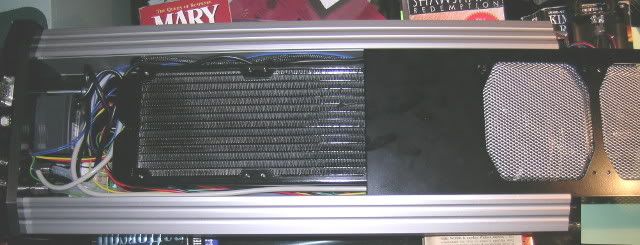
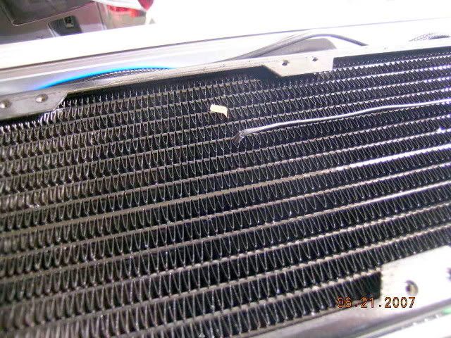
Here is a close-up of the 360 radiator and the temp probe they have placed to measure the air temp after leaving the radiator.
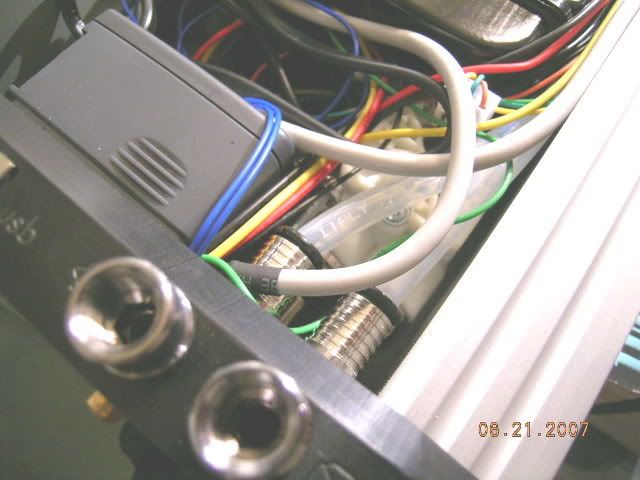
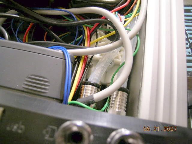
The water tubes go along both sides of the radiator. Seems strange, but I guess we will have to wait till further disassembly to see what's up. The wires also are routed through this area on both sides as well (more sleeving and shortening). Using bigger tubing looks kind of tight in here. Guess I got to order the tubing and see what we see.
The circuit board you see here is the pump controller board and is piggy backed to the Aquaero. In addition it has a ribbon cable to allow control and create a feed back loop to the software/hardware.
More later when I have time to process more pics.
Here you can see me sliding off the back panel.
In case you were wondering how they did that fancy grill this is it. AC has started selling this grill in some pre-made cases so I think it is only a matter of time before they sell them by themselves.
Here's looking at the bottom inside of the Aquaduct.
Here you can see the Eheim Compact 600 pump and the DigMesa flow meter is barely visible under the tubing on the right side. I take back what I said earlier about their good wiring skills. All these wires are going to have to be customized to the proper length and sleeved. How about a plexi back plate here?
Here is a close-up of the 360 radiator and the temp probe they have placed to measure the air temp after leaving the radiator.
The water tubes go along both sides of the radiator. Seems strange, but I guess we will have to wait till further disassembly to see what's up. The wires also are routed through this area on both sides as well (more sleeving and shortening). Using bigger tubing looks kind of tight in here. Guess I got to order the tubing and see what we see.
The circuit board you see here is the pump controller board and is piggy backed to the Aquaero. In addition it has a ribbon cable to allow control and create a feed back loop to the software/hardware.
More later when I have time to process more pics.
seems like your aquaduct is R.I.P. ? ;D
Multiswitch Script Generator NG | Aquaero2Multiswitch | Ae Relais | Verkaufe AT Plexi!
*pfew* ;D
Multiswitch Script Generator NG | Aquaero2Multiswitch | Ae Relais | Verkaufe AT Plexi!
So how are things coming along here?
Is this Aquaduct nr 4 which never got puck back together (succesfully), or is work still pending?
I've just purchased a unit and am wondering if the supplied pump (Eheim Compact 600 if I'm not mistaken?) is any good?
I have a Innovatek HPPS 12V pump as well, would it be a good idea to add that to the flow cycle, either as extra pump or as the pump and somehow disable the compact?
Zitat von »JorisS«
So how are things coming along here?
Is this Aquaduct nr 4 which never got puck back together (succesfully), or is work still pending?
I've just purchased a unit and am wondering if the supplied pump (Eheim Compact 600 if I'm not mistaken?) is any good?
I have a Innovatek HPPS 12V pump as well, would it be a good idea to add that to the flow cycle, either as extra pump or as the pump and somehow disable the compact?
Just been busy with other things and making money.

The pump is listed as type 1001.760 with 1.3 meters of head. It's not a standard Eheim 600 from what I can tell. If you wish to disable it you can unplug it from the Aquaero board and remove the impeller. However, you must leave in the pump unless you have a mill hand to make some fancy parts to cover the pump hole in the bottom block. There is definitely no way you are going to be able to fit a HPPS pump in there even if you take the Eheim out! You could put a HHPS inline between the Aquaduct and the computer though.
Just been busy with other things and making money.
The pump is listed as type 1001.760 with 1.3 meters of head. It's not a standard Eheim 600 from what I can tell. If you wish to disable it you can unplug it from the Aquaero board and remove the impeller. However, you must leave in the pump unless you have a mill hand to make some fancy parts to cover the pump hole in the bottom block. There is definitely no way you are going to be able to fit a HPPS pump in there even if you take the Eheim out! You could put a HHPS inline between the Aquaduct and the computer though.
Well considering your efforts and the fact several ppl tried to open up the Aquaduct and never got it back together... I'm not considering opening the thing up. So either if the pump can be disabled through the software that'd be an option, otherwise an inline pump solution. Or both, but I don't know if one pump pushing harder would actually kill the slower pump, if it starts spinning to fast? Or is that silly thinking

Currently I have a flowrate of about 60-65 l/hour, with a system build up of the Aquaduct 360XT, Tygon 1/4"ID tubing, D-Tek Fuzion CPU block and a EK R600 for HD2900XT GPU block. I don't know if that's good or bad or somewhere in between.
Idle temps currently at 37 degrees for my E6600 ES at stock speed, water temp 28.8 degrees (both in and out). Air temperature about 24 degrees.
Have to say that's with the default EEprom values or something. So pump is currently actually pumping only 45l/h and fans are turned off ???
The forum software keeps trying to remind me that the last post in this thread was 503 days ago and wants me to consider creating a new thread. Then I would have to re-post all those pics again. 
I am awaiting some new AC parts for my Feeding Frenzy project that is being renewed (some might call it being dredged up). So while I am waiting for the parts to get here I decided to finish up on my Aquaduct 360. I quit working on it because I was a little dismayed that it had about two meters of plug &cool tubing that I figured was unnecessary. Then a few months ago I dragged it out and couldn't remember where some of the wires went. 
Stephan from AC Berlin has an Aquaduct mod thread over on bit-tech and one of the pics inspired me to really think about a few things. After deciding in for a penny in for a pound I got busy and tore it all
apart. Now it seems obvious where everything goes again.
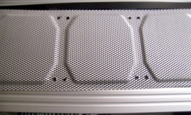
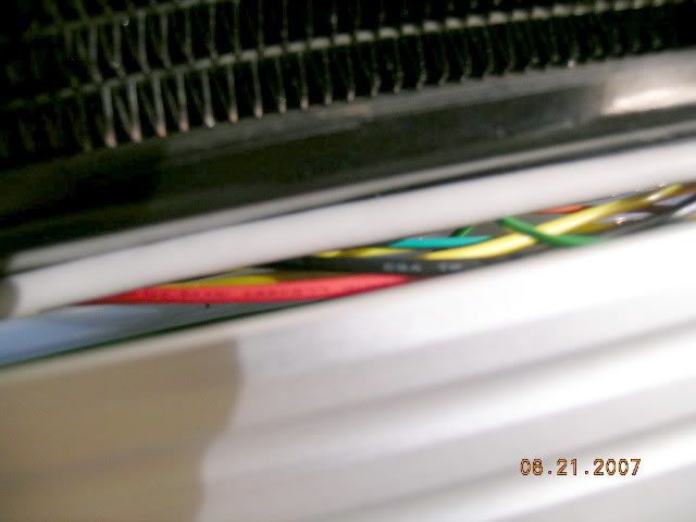
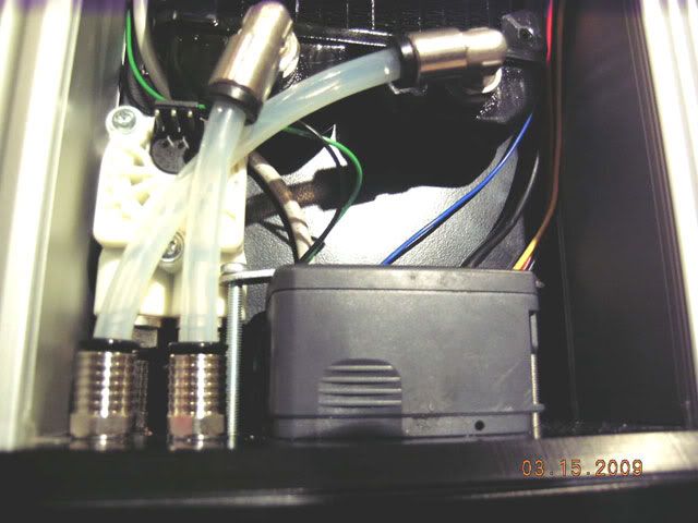
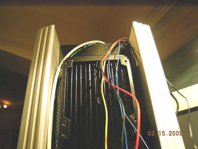
Keep in mind that my Aquaduct 360 is considerably different from what you would buy today. So I decided the first thing to do would be to get rid of the extraneous tubing. In the following pic you can see the water lines coming down the right side. What you don't see is that the tubing wraps all the way around the top and back down the other side to the reservoir tanks on the bottom of the Aquaduct.
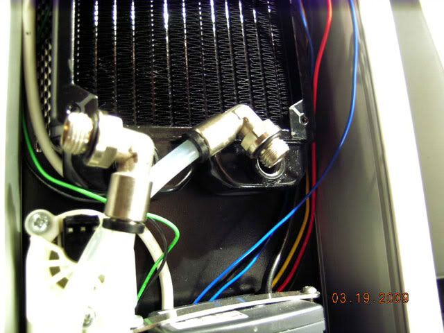
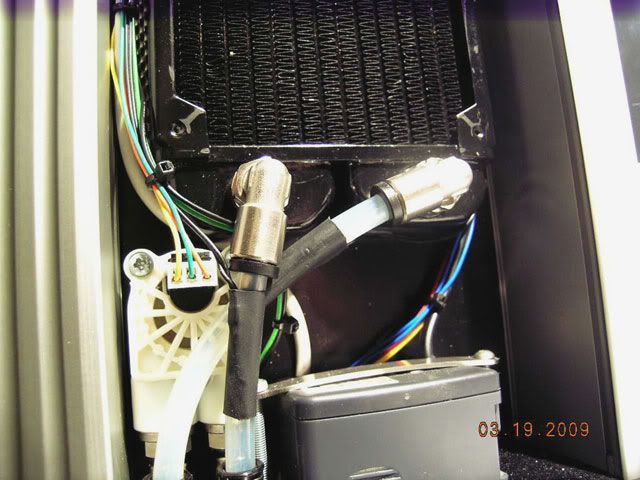
In the next pic I have done some things that may not be so readily apparent unless you are a close observer. The apparent part is that now the tubes coming off the radiator and go directly into the bottom water block. Getting rid of two meters of tubing has just got to be an improvement. If your wondering how you get the tubing on when it is so close together it is actually quite simple so long as you think out of the box. You first use some scrap tubing to get the length right as you might have to bend the tubing severely to get it in the fittings correctly. Then you get the the tubing out and cut a new piece based on the length you just figured out with the scrap tubing. Now you unbolt the 90* fittings from the radiator and insert the tubing really easy. Then you just screw in the 90* fittings and your almost done. More on that later.
Still haven't figured out what else I did? Hint: Compare the last two photos. Got to get off to bed and tomorrow I will be working on the wiring.
I am awaiting some new AC parts for my Feeding Frenzy project that is being renewed (some might call it being dredged up).
So while I am waiting for the parts to get here I decided to finish up on my Aquaduct 360. I quit working on it because I was a little dismayed that it had about two meters of plug &cool tubing that I figured was unnecessary. Then a few months ago I dragged it out and couldn't remember where some of the wires went. Stephan from AC Berlin has an Aquaduct mod thread over on bit-tech and one of the pics inspired me to really think about a few things. After deciding in for a penny in for a pound I got busy and tore it all
apart. Now it seems obvious where everything goes again.
Keep in mind that my Aquaduct 360 is considerably different from what you would buy today. So I decided the first thing to do would be to get rid of the extraneous tubing. In the following pic you can see the water lines coming down the right side. What you don't see is that the tubing wraps all the way around the top and back down the other side to the reservoir tanks on the bottom of the Aquaduct.
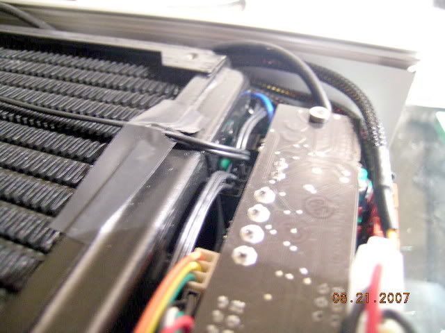
In the next pic I have done some things that may not be so readily apparent unless you are a close observer. The apparent part is that now the tubes coming off the radiator and go directly into the bottom water block. Getting rid of two meters of tubing has just got to be an improvement. If your wondering how you get the tubing on when it is so close together it is actually quite simple so long as you think out of the box. You first use some scrap tubing to get the length right as you might have to bend the tubing severely to get it in the fittings correctly. Then you get the the tubing out and cut a new piece based on the length you just figured out with the scrap tubing. Now you unbolt the 90* fittings from the radiator and insert the tubing really easy. Then you just screw in the 90* fittings and your almost done. More on that later.
Still haven't figured out what else I did? Hint: Compare the last two photos. Got to get off to bed and tomorrow I will be working on the wiring.
First, thank you for litereally "taking the unit apart" for us to see what the beast looks like.
Second, you have much greater courage than I. After spending $500+ for my unit I would never ever take it apart. At age 78 I have been living my life on the principle "If it ain't broke DO NOT fix it"!
I eagerly await the next installment of this thread!
Thank you again for sharing.
Second, you have much greater courage than I. After spending $500+ for my unit I would never ever take it apart. At age 78 I have been living my life on the principle "If it ain't broke DO NOT fix it"!
I eagerly await the next installment of this thread!
Thank you again for sharing.
R.V.Brown, Sr.
Chambersburg, PA USA
Chambersburg, PA USA
When I first got my Gemini G-11(11" telescope and computer guided mount) the first thing I did was to take it all apart to see what I could improve. I tend to ignore anything that says do not open.Second, you have much greater courage than I. After spending $500+ for my unit I would never ever take it apart. At age 78 I have been living my life on the principle "If it ain't broke DO NOT fix it"!
Without all the meters of water tubes there is much more room for wires. I'm sitting here right now deciding whether to bundle them in two sets of lines going up each side or individually sleeve them. I think the best way is to do them like I did the PSU/HD wires in FFI.Damn I spent a good part of the afternoon reading that work log. You got some good ideas going on there.I love to tinker but that took a lot of guts to take that rad assembly apart.
That last pic looks a lot neater where'd all the wires go?
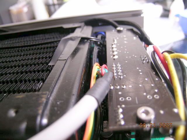
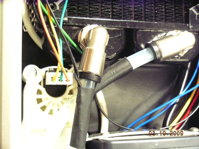
Had a little free time this evening and thought vI would finish up with the water tubing and do a little wiring. From previous pics you have probably seen some NTC thermistors hanging out of the radiator like below. I gave it some thought as there were two of these temp sensors. I figure one for incoming air and one for outgoing air. Decided to only put back one of the temp sensors as I can't see having two to be of any value. In fact I am debating whether one is of any value in measuring the incoming (or ambient) temperature. Having a NTC thermistor stuck in the water fins makes one wonder just what is getting measured. Is it the air temp, the water temp, or some value inbetween? 
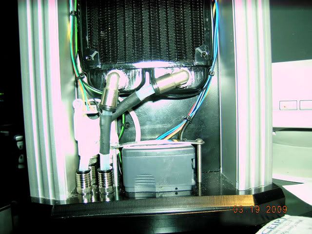
As mentioned previously getting those short tubes on & off can be a major pain without bending the tubes. Here is where I take off the fittings, insert the tubes, and then get ready to screw them back on while the tubing is already installed.
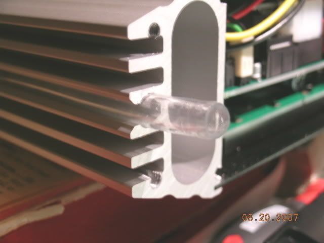
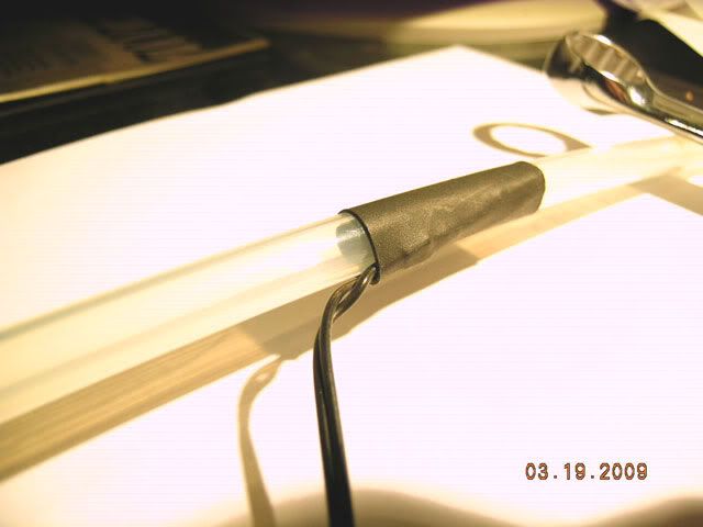
One of the other strange things about this version of the Aquaduct is how they measure the water temps. Normally in an AC loop you would have a temp sensor actually immersed in the water through a T fitting. There isn't a lot of room for a T fitting and believe me when I say I tried for a long time as I am sure AC did as well. So the only way to measure the temp is by measuring the tube the water is in as it travels through the tube. So you can see in the following pic how they managed this. Just a plain old NTC thermistor attached with a piece of heat shrink.
So now that we have ascertained the correct length of tubing previously we can now cut the tubing with a good deal of accuracy and use the stock temp sensors.
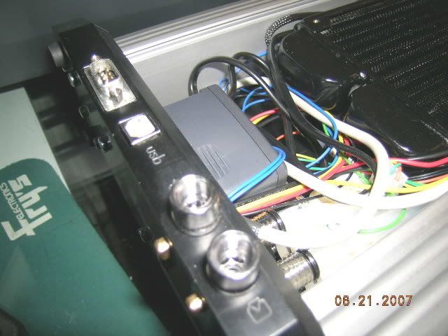
The next thing to do is to figure out which wires need to go up what side so that they are close to the correct Aquaero connections.
For the time being I decided to just route the wires where I wanted them and to use some cable ties to clean things up a bit. I figure the Aquaduct will be put back together and taken apart a lot from here on out as I make some other modding decisions. Once I figure it all out I will go back and do my sleeving magic for my own edification.
So that wraps things up till I decide what I am going to do with the sides and fan covers.
As mentioned previously getting those short tubes on & off can be a major pain without bending the tubes. Here is where I take off the fittings, insert the tubes, and then get ready to screw them back on while the tubing is already installed.
One of the other strange things about this version of the Aquaduct is how they measure the water temps. Normally in an AC loop you would have a temp sensor actually immersed in the water through a T fitting. There isn't a lot of room for a T fitting and believe me when I say I tried for a long time as I am sure AC did as well. So the only way to measure the temp is by measuring the tube the water is in as it travels through the tube. So you can see in the following pic how they managed this. Just a plain old NTC thermistor attached with a piece of heat shrink.
So now that we have ascertained the correct length of tubing previously we can now cut the tubing with a good deal of accuracy and use the stock temp sensors.
The next thing to do is to figure out which wires need to go up what side so that they are close to the correct Aquaero connections.
For the time being I decided to just route the wires where I wanted them and to use some cable ties to clean things up a bit. I figure the Aquaduct will be put back together and taken apart a lot from here on out as I make some other modding decisions. Once I figure it all out I will go back and do my sleeving magic for my own edification.
So that wraps things up till I decide what I am going to do with the sides and fan covers.
A solution to the water temp probe if you cannot fit a tee can be found in the german speaking watercooling forum. I saw an inline water sensor yesterday there, its sorta like a doughnut shaped fitting with female threads on bothe ends for fittings. The sensor is part of the fitting and is very streamlined. You might wanna chack that one out. HTH.
- 1
- 2
-